CAMSHAFT POSITION SENSOR REMOVAL
PROCEDURE
-
REMOVE V-BANK COVER SUB-ASSEMBLY
-
REMOVE ENGINE ROOM SIDE COVER
-
REMOVE AIR CLEANER CAP WITH AIR CLEANER HOSE
-
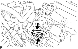
REMOVE VVT SENSOR (for Intake Side of Bank 1)
-
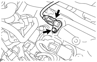
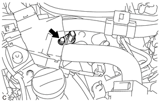
Disconnect the VVT sensor connector.
-
Remove the bolt and VVT sensor from the cylinder head cover sub-assembly.
-
-
REMOVE VVT SENSOR (for Exhaust Side of Bank 1)
-
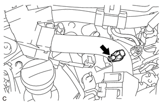
Disconnect the VVT sensor connector.
-
Remove the bolt and VVT sensor from the cylinder head cover sub-assembly.
-
-
DISCONNECT ENGINE WIRE
-
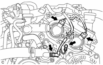
Disengage the clamp.
-
Disconnect the 2 camshaft timing oil control solenoid assembly connectors and water inlet with thermostat sub-assembly connector.
-
Remove the bolt to disconnect the engine wire from the timing chain cover assembly.
-
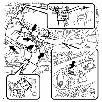
Disengage the 3 clamps.
-
Remove the 2 nuts to disconnect the engine wire from the cylinder head cover sub-assembly LH.
-
Disconnect the 2 VVT sensor connectors and 2 ignition coil assembly connectors.
-
-
REMOVE VVT SENSOR (for Intake Side of Bank 2)
-
Remove the bolt and VVT sensor from the cylinder head cover sub-assembly LH.
-
-
REMOVE VVT SENSOR (for Exhaust Side of Bank 2)
-
Remove the bolt and VVT sensor from the cylinder head cover sub-assembly LH.
-