SFI SYSTEM(w/o Canister Pump Module), Diagnostic DTC:P032511, P033011
| DTC Code | DTC Name |
|---|---|
| P032511 | Knock Sensor 1 Bank 1 or Single Sensor Circuit Short to Ground |
| P033011 | Knock Sensor 2 Bank 2 Circuit Short to Ground |
DESCRIPTION
A flat-type knock control sensor (non-resonant type) has a structure that can detect vibrations between approximately 5 and 15 kHz.
The knock control sensor is fitted onto the engine block to detect engine knocking.
The knock control sensor contains a piezoelectric element which generates a voltage when it becomes deformed.
The voltage is generated when the engine block vibrates due to knocking. Any occurrence of engine knocking can be suppressed by delaying the ignition timing.
Tech Tips
When DTC P032511 or P033011 is stored, the ECM enters fail-safe mode. During fail-safe mode, the ignition timing is delayed to its maximum retardation. Fail-safe mode continues until the engine switch is turned off.
| DTC No. | Detection Item | DTC Detection Condition | Trouble Area | MIL | Memory | Note |
|---|---|---|---|---|---|---|
| P032511 | Knock Sensor 1 Bank 1 or Single Sensor Circuit Short to Ground | The knock control sensor (bank 1) output voltage is less than 0.5 V for 1 second or more (1 trip detection logic). |
|
Comes on | DTC stored | SAE Code: P0327 |
| P033011 | Knock Sensor 2 Bank 2 Circuit Short to Ground | The knock control sensor (bank 2) output voltage is less than 0.5 V for 1 second or more (1 trip detection logic). |
|
Comes on | DTC stored | SAE Code: P0332 |
Reference: Inspection using an oscilloscope
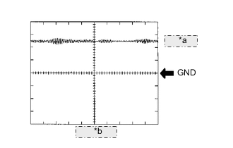
| *a | 1 V/DIV. |
| *b | 1 ms./DIV. |
Tech Tips
The correct waveform is as shown.
| ECM Terminal Name | Between KNK1 and EKNK Between KNK2 and EKN2 |
| Tester Range | 1 V/DIV., 1 ms./DIV. |
| Condition | Engine speed maintained at 4000 rpm after warming up engine |
MONITOR DESCRIPTION
If the output voltage transmitted by the knock control sensor remains low for 1 second or more, the ECM interprets this as a malfunction in the sensor circuit, and stores this DTC.
MONITOR STRATEGY
| Frequency of Operation | Continuous |
CONFIRMATION DRIVING PATTERN
-
Connect the GTS to the DLC3.
-
Turn the engine switch on (IG).
-
Turn the GTS on.
-
Clear the DTCs (even if no DTCs are stored, perform the clear DTC procedure).
-
Turn the engine switch off and wait for at least 30 seconds.
-
Start the engine and wait 5 minutes.
-
Turn the GTS on.
-
Enter the following menus: Powertrain / Engine / Trouble Codes.
-
Read the pending DTCs.
Tech Tips
-
If a pending DTC is output, the system is malfunctioning.
-
If a pending DTC is not output, perform the following procedure.
-
-
Enter the following menus: Powertrain / Engine / Utility / All Readiness.
-
Input the DTC: P032511 or P033011.
-
Check the DTC judgment result.
GTS Display Description NORMAL
-
DTC judgment completed
-
System normal
ABNORMAL
-
DTC judgment completed
-
System abnormal
INCOMPLETE
-
DTC judgment not completed
-
Perform driving pattern after confirming DTC enabling conditions
Tech Tips
-
If the judgment result is NORMAL, the system is normal.
-
If the judgment result is ABNORMAL, the system is malfunctioning.
-
If the judgment result is INCOMPLETE, idle the engine for 5 minutes and check the DTC judgment result again.
-
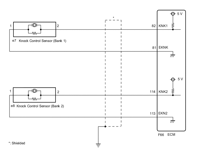
WIRING DIAGRAM
CAUTION / NOTICE / HINT
Tech Tips
-
DTC P032511 is for the bank 1 knock control sensor circuit.
-
DTC P033011 is for the bank 2 knock control sensor circuit.
-
Bank 1 refers to the bank that includes the No. 1 cylinder*.
*: The No. 1 cylinder is the cylinder which is farthest from the transmission.
-
Bank 2 refers to the bank that does not include the No. 1 cylinder.
-
Read freeze frame data using the GTS. The ECM records vehicle and driving condition information as freeze frame data the moment a DTC is stored. When troubleshooting, freeze frame data can help determine if the vehicle was moving or stationary, if the engine was warmed up or not, if the air fuel ratio was lean or rich, and other data from the time the malfunction occurred.
PROCEDURE
-
CHECK TERMINAL VOLTAGE (POWER SOURCE OF KNOCK CONTROL SENSOR)
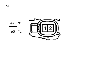
*a Front view of wire harness connector
(to Knock Control Sensor)
*b Bank 1 *c Bank 2
-
Disconnect the knock control sensor connector.
-
Turn the engine switch on (IG).
-
Measure the voltage according to the value(s) in the table below.
Standard Voltage Tester Connection Condition Specified Condition e7-1 - e7-2 Engine switch on (IG) 4.5 to 5.5 V e8-1 - e8-2 Engine switch on (IG) 4.5 to 5.5 V Result Proceed to OK NG
NG 
CHECK HARNESS AND CONNECTOR (KNOCK CONTROL SENSOR - ECM) Click here
OK 
-
-
INSPECT KNOCK CONTROL SENSOR
-
Inspect the knock control sensor.
Result Proceed to OK NG
OK
GO TO STEP 5 Click here
NG 
REPLACE KNOCK CONTROL SENSOR Click here
-
-
CHECK HARNESS AND CONNECTOR (KNOCK CONTROL SENSOR - ECM)
-
Disconnect the knock control sensor connector.
-
Disconnect the ECM connector.
-
Measure the resistance according to the value(s) in the table below.
Standard Resistance Tester Connection Condition Specified Condition e7-2 or F66-82 (KNK1) - Body ground Always 10 kΩ or higher e8-2 or F66-114 (KNK2) - Body ground Always 10 kΩ or higher Result Proceed to OK NG
NG
REPAIR OR REPLACE HARNESS OR CONNECTOR
OK
-
-
CLEAR DTC
-
Connect the GTS to the DLC3.
-
Turn the engine switch on (IG).
-
Turn the GTS on.
-
Clear the DTC.
Powertrain > Engine > Clear DTCs -
Turn the engine switch off and wait for at least 30 seconds.
Result Proceed to NEXT
NEXT
-
-
CHECK WHETHER DTC OUTPUT RECURS (DTC P032511 OR P033011)
-
Drive the vehicle in accordance with the driving pattern described in Confirmation Driving Pattern.
-
Enter the following menus: Powertrain / Engine / Trouble Codes.
-
Read the DTCs.
Powertrain > Engine > Trouble CodesResult Result Proceed to DTCs are not output A DTC P032511 or P033011 is output B
A
CHECK FOR INTERMITTENT PROBLEMS Click here
B
REPLACE ECM Click here
-