SFI SYSTEM(w/ Canister Pump Module), Diagnostic DTC:P036511, P036515, P039011, P039015
| DTC Code | DTC Name |
|---|---|
| P036511 | Camshaft Position Sensor "B" Bank 1 Circuit Short to Ground |
| P036515 | Camshaft Position Sensor "B" Bank 1 Circuit Short to Battery or Open |
| P039011 | Camshaft Position Sensor "B" Bank 2 Circuit Short to Ground |
| P039015 | Camshaft Position Sensor "B" Bank 2 Circuit Short to Battery or Open |
DESCRIPTION
The VVT sensor (for exhaust camshaft) (EV1, EV2 signal) consists of a magnet and MRE (Magneto Resistance Element).
The exhaust camshaft has a timing rotor for the VVT sensor. When the exhaust camshaft rotates, changes occur in the air gaps between the timing rotor and MRE, which affects the magnetic field. As a result, the resistance of the MRE material fluctuates. The VVT sensor converts the camshaft rotation data to pulse signals, uses the pulse signals to determine the camshaft angle, and sends it to the ECM. Then the ECM uses this data to control fuel injection duration, injection timing and the Variable Valve Timing (VVT) system.
| DTC No. | Detection Item | DTC Detection Condition | Trouble Area | MIL | Memory | Note |
|---|---|---|---|---|---|---|
| P036511 | Camshaft Position Sensor "B" Bank 1 Circuit Short to Ground | The VVT sensor (for exhaust camshaft of bank 1) output voltage is less than 0.3 V for 4 seconds or more (1 trip detection logic). |
|
Comes on | DTC stored | SAE Code: P0367 |
| P036515 | Camshaft Position Sensor "B" Bank 1 Circuit Short to Battery or Open | The VVT sensor (for exhaust camshaft of bank 1) output voltage is higher than 4.7 V for 4 seconds or more (1 trip detection logic). |
|
Comes on | DTC stored | SAE Code: P0368 |
| P039011 | Camshaft Position Sensor "B" Bank 2 Circuit Short to Ground | The VVT sensor (for exhaust camshaft of bank 2) output voltage is less than 0.3 V for 4 seconds or more (1 trip detection logic). |
|
Comes on | DTC stored | SAE Code: P0392 |
| P039015 | Camshaft Position Sensor "B" Bank 2 Circuit Short to Battery or Open | The VVT sensor (for exhaust camshaft of bank 2) output voltage is higher than 4.7 V for 4 seconds or more (1 trip detection logic). |
|
Comes on | DTC stored | SAE Code: P0393 |
-
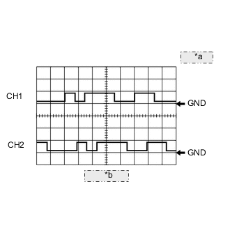
*a 5 V/DIV. *b 20 ms./DIV. Reference: Inspection using an oscilloscope.
Tech Tips
-
The correct waveform is as shown.
-
EV1 stands for the VVT sensor (for exhaust camshaft of bank 1) signal, and EV2 stands for the VVT sensor (for exhaust camshaft of bank 2) signal.
ECM Terminal Name CH1: Between EV1+ and ETHW
CH2: Between EV2+ and ETHW
Tester Range 5 V/DIV., 20 ms./DIV. Condition Idling -
MONITOR DESCRIPTION
If the output voltage transmitted by the VVT sensor (for exhaust camshaft) remains low or high, the ECM interprets this as a malfunction in the sensor circuit, illuminates the MIL and stores a DTC.
MONITOR STRATEGY
| Required Sensors/Components (Main) | VVT sensor (for exhaust camshaft) |
| Required Sensors/Components (Related) | Crankshaft position sensor |
| Frequency of Operation | Continuous |
CONFIRMATION DRIVING PATTERN
-
Connect the GTS to the DLC3.
-
Turn the engine switch on (IG).
-
Turn the GTS on.
-
Clear the DTCs (even if no DTCs are stored, perform the clear DTC procedure).
-
Turn the engine switch off and wait for at least 30 seconds.
-
Turn the engine switch on (IG) [A].
-
Turn the GTS on.
-
Wait for 5 seconds or more [B].
-
Enter the following menus: Powertrain / Engine / Trouble Codes [C].
-
Read the pending DTCs.
Tech Tips
-
If a pending DTC is output, the system is malfunctioning.
-
If a pending DTC is not output, perform the following procedure.
-
-
Enter the following menus: Powertrain / Engine / Utility / All Readiness.
-
Input the DTC: P036511, P036515, P039011 or P039015.
-
Check the DTC judgment result.
GTS Display Description NORMAL
-
DTC judgment completed
-
System normal
ABNORMAL
-
DTC judgment completed
-
System abnormal
INCOMPLETE
-
DTC judgment not completed
-
Perform driving pattern after confirming DTC enabling conditions
Tech Tips
-
If the judgment result is NORMAL, the system is normal.
-
If the judgment result is ABNORMAL, the system is malfunctioning.
-
WIRING DIAGRAM
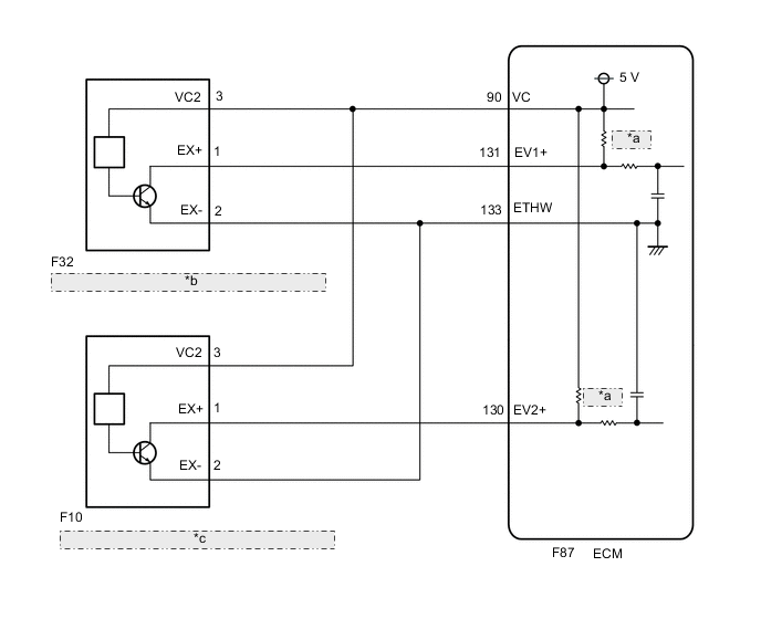
| *a | 1.5 kΩ |
| *b | VVT Sensor (for Exhaust Camshaft of Bank 1) |
| *c | VVT Sensor (for Exhaust Camshaft of Bank 2) |
CAUTION / NOTICE / HINT
Tech Tips
-
Bank 1 refers to the bank that includes the No. 1 cylinder*.
*: The No. 1 cylinder is the cylinder which is farthest from the transmission.
-
Bank 2 refers to the bank that does not include the No. 1 cylinder.
-
Read freeze frame data using the GTS. The ECM records vehicle and driving condition information as freeze frame data the moment a DTC is stored. When troubleshooting, freeze frame data can help determine if the vehicle was moving or stationary, if the engine was warmed up or not, if the air fuel ratio was lean or rich, and other data from the time the malfunction occurred.
PROCEDURE
-
CHECK HARNESS AND CONNECTOR
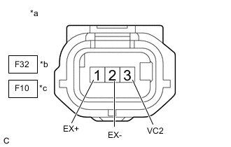
*a Front view of wire harness connector
(to VVT Sensor (for Exhaust Camshaft))
*b Bank 1 *c Bank 2 Tech Tips
Make sure that the connector is properly connected. If it is not, securely connect it and check for DTCs again.
-
Disconnect the VVT sensor (for exhaust camshaft) connector.
-
Turn the engine switch on (IG).
-
Measure the voltage according to the value(s) in the table below.
Standard Voltage Tester Connection Condition Specified Condition F32-3 (VC2) - Body ground Engine switch on (IG) 4.5 to 5.5 V F10-3 (VC2) - Body ground Engine switch on (IG) 4.5 to 5.5 V F32-1 (EX+) - Body ground Engine switch on (IG) 3.0 to 5.0 V F10-1 (EX+) - Body ground Engine switch on (IG) 3.0 to 5.0 V -
Turn the engine switch off and wait for at least 30 seconds.
-
Measure the resistance according to the value(s) in the table below.
Standard Resistance Tester Connection Condition Specified Condition F32-3 (VC2) - F32-1 (EX+) Engine switch off 1.425 to 1.575 kΩ F10-3 (VC2) - F10-1 (EX+) Engine switch off 1.425 to 1.575 kΩ F32-2 (EX-) - Body ground Always Below 1 Ω F10-2 (EX-) - Body ground Always Below 1 Ω Result Proceed to OK NG
OK 
REPLACE VVT SENSOR (FOR EXHAUST CAMSHAFT) Click here
NG 
-
-
CHECK HARNESS AND CONNECTOR (VVT SENSOR (FOR EXHAUST CAMSHAFT) - ECM)
-
Disconnect the VVT sensor (for exhaust camshaft) connector.
-
Disconnect the ECM connector.
-
Measure the resistance according to the value(s) in the table below.
Standard Resistance Tester Connection Condition Specified Condition F32-1 (EX+) - F87-131 (EV1+) Always Below 1 Ω F32-2 (EX-) - F87-133 (ETHW) Always Below 1 Ω F32-3 (VC2) - F87-90 (VC) Always Below 1 Ω F10-1 (EX+) - F87-130 (EV2+) Always Below 1 Ω F10-2 (EX-) - F87-133 (ETHW) Always Below 1 Ω F10-3 (VC2) - F87-90 (VC) Always Below 1 Ω F32-1 (EX+) or F87-131 (EV1+) - Body ground and other terminals Always 10 kΩ or higher F32-2 (EX-) or F87-133 (ETHW) - Body ground and other terminals Always 10 kΩ or higher F32-3 (VC2) or F87-90 (VC) - Body ground and other terminals Always 10 kΩ or higher F10-1 (EX+) or F87-130 (EV2+) - Body ground and other terminals Always 10 kΩ or higher F10-2 (EX-) or F87-133 (ETHW) - Body ground and other terminals Always 10 kΩ or higher F10-3 (VC2) or F87-90 (VC) - Body ground and other terminals Always 10 kΩ or higher Result Proceed to OK NG
OK
REPLACE ECM Click here
NG
REPAIR OR REPLACE HARNESS OR CONNECTOR
-