SFI SYSTEM(w/ Canister Pump Module), Diagnostic DTC:P01201C
| DTC Code | DTC Name |
|---|---|
| P01201C | Throttle / Pedal Position Sensor / Switch "A" Circuit Voltage Out of Range |
DESCRIPTION
Refer to DTC P012011.
| DTC No. | Detection Item | DTC Detection Condition | Trouble Area | MIL | Memory | Note |
|---|---|---|---|---|---|---|
| P01201C | Throttle / Pedal Position Sensor / Switch "A" Circuit Voltage Out of Range | The difference between the output voltage of VTA1 and VTA2 is less than 0.8 V, or higher than 1.6 V for less than 2 seconds (1 trip detection logic). |
|
Comes on | DTC stored | SAE Code: P0121 |
MONITOR DESCRIPTION
The ECM uses the throttle position sensor to monitor the throttle valve opening angle. There are several checks that the ECM performs to confirm the proper operation of the throttle position sensor.
This sensor transmits two signals: VTA1 and VTA2. VTA1 is used to detect the throttle opening angle and VTA2 is used to detect malfunctions in VTA1. The ECM performs several checks to confirm the proper operation of the throttle position sensor and VTA1.
For each throttle opening angle, a specific voltage difference is expected between the outputs of VTA1 and VTA2. If the output voltage difference between the two signals deviates from the normal operating range, the ECM interprets this as a malfunction of the throttle position sensor, illuminates the MIL and stores a DTC.
MONITOR STRATEGY
| Frequency of Operation | Continuous |
CONFIRMATION DRIVING PATTERN
-
Connect the GTS to the DLC3.
-
Turn the engine switch on (IG).
-
Turn the GTS on.
-
Clear the DTCs (even if no DTCs are stored, perform the clear DTC procedure).
-
Turn the engine switch off and wait for at least 30 seconds.
-
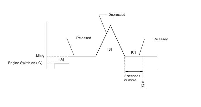
Turn the engine switch on (IG) [A].
-
Turn the GTS on.
-
Start the engine.
-
With the vehicle stationary, fully depress and release the accelerator pedal [B].
-
Idle the engine for 2 seconds or more [C].
-
Enter the following menus: Powertrain / Engine / Trouble Codes [D].
-
Read the pending DTCs.
Tech Tips
-
If a pending DTC is output, the system is malfunctioning.
-
If a pending DTC is not output, perform the following procedure.
-
-
Enter the following menus: Powertrain / Engine / Utility / All Readiness.
-
Input the DTC: P01201C.
-
Check the DTC judgment result.
GTS Display Description NORMAL
-
DTC judgment completed
-
System normal
ABNORMAL
-
DTC judgment completed
-
System abnormal
INCOMPLETE
-
DTC judgment not completed
-
Perform driving pattern after confirming DTC enabling conditions
Tech Tips
-
If the judgment result is NORMAL, the system is normal.
-
If the judgment result is ABNORMAL, the system is malfunctioning.
-
If the judgment result is INCOMPLETE, perform steps [B] through [D] again.
-
FAIL-SAFE
When this DTC is stored, the ECM enters fail-safe mode. During fail-safe mode, the ECM cuts the current to the throttle actuator, and the throttle valve is returned to a 7° throttle valve opening angle by the return spring. The ECM then adjusts the engine output by controlling the fuel injection (intermittent fuel-cut) and ignition timing, in accordance with the accelerator pedal angle, to allow the vehicle to continue running at a minimal speed. If the accelerator pedal is depressed firmly and gently, the vehicle can be driven slowly.
Fail-safe mode continues until a pass condition is detected, and the engine switch is turned off.
CAUTION / NOTICE / HINT
Tech Tips
-
DTC P01201C is stored when the VTA1 and VTA2 output voltages are not consistent with the sensor characteristics. Therefore, check the Freeze Frame Data for this DTC. Use the following formula to confirm the relative differences in voltage.
Characteristic Sensor Output VTA2 x 0.8 is approximately equal to VTA1 + 1.11 V VTA1: Throttle Position Sensor No.1 Voltage VTA2: Throttle Position Sensor No.2 Voltage -
Read Freeze Frame Data using the GTS. The ECM records vehicle and driving condition information as Freeze Frame Data the moment a DTC is stored. When troubleshooting, Freeze Frame Data can help determine if the vehicle was moving or stationary, if the engine was warmed up or not, if the air fuel ratio was lean or rich, and other data from the time the malfunction occurred.
PROCEDURE
-
CHECK HARNESS AND CONNECTOR (THROTTLE POSITION SENSOR - ECM)
-
Disconnect the throttle body with motor assembly connector.
-
Disconnect the ECM connector.
-
Measure the resistance according to the value(s) in the table below.
Standard Resistance Tester Connection Condition Specified Condition F21-5 (VC) - F87-121 (VCTA) Always Below 1 Ω F21-6 (VTA) - F87-122 (VTA1) Always Below 1 Ω F21-4 (VTA2) - F87-89 (VTA2) Always Below 1 Ω F21-3 (E2) - F87-120 (ETA) Always Below 1 Ω F21-5 (VC) or F87-121 (VCTA) - Body ground and other terminals Always 10 kΩ or higher F21-6 (VTA) or F87-122 (VTA1) - Body ground and other terminals Always 10 kΩ or higher F21-4 (VTA2) or F87-89 (VTA2) - Body ground and other terminals Always 10 kΩ or higher -
Inspect the condition of the terminals of the connectors.
Result Proceed to OK NG
OK 
GO TO STEP 5 Click here
NG 
-
-
REPAIR OR REPLACE HARNESS OR CONNECTOR
-
Repair or replace the wire harness or connector.
Result Proceed to NEXT
NEXT
-
-
CLEAR DTC
-
Connect the GTS to the DLC3.
-
Turn the engine switch on (IG).
-
Turn the GTS on.
-
Clear the DTCs.
Powertrain > Engine > Clear DTCs -
Turn the engine switch off and wait for at least 30 seconds.
Result Proceed to NEXT
NEXT
-
-
CHECK WHETHER DTC OUTPUT RECURS (DTC P01201C)
-
Drive the vehicle in accordance with the driving pattern described in Confirmation Driving Pattern.
-
Enter the following menus: Powertrain / Engine / Trouble Codes.
-
Read the DTCs.
Powertrain > Engine > Trouble CodesResult Result Proceed to DTCs are not output A DTC P01201C is output B
A 
END
B
-
-
CHECK HARNESS AND CONNECTOR (RESISTANCE OF ECM)
-
Disconnect the throttle body with motor assembly connector.
-
Measure the resistance according to the value(s) in the table below.
Standard Resistance Tester Connection Condition Specified Condition F21-5 (VC) - F21-6 (VTA) Engine switch off 190 to 210 kΩ F21-5 (VC) - F21-4 (VTA2) Engine switch off 190 to 210 kΩ Tech Tips
Perform "Inspection After Repair" after replacing the throttle body with motor assembly.
Result Proceed to OK NG
OK
REPLACE THROTTLE BODY WITH MOTOR ASSEMBLY Click here
NG
REPLACE ECM Click here
-