SFI SYSTEM(w/ Canister Pump Module), Diagnostic DTC:P010014, P010016
| DTC Code | DTC Name |
|---|---|
| P010014 | Mass or Volume Air Flow Sensor "A" Circuit Short to Ground or Open |
| P010016 | Mass or Volume Air Flow Sensor "A" Circuit Voltage Below Threshold |
DESCRIPTION
Refer to DTC P010012.
Tech Tips
When any of these DTCs are stored, the ECM enters fail-safe mode. During fail-safe mode, boost prohibited and the ignition timing is calculated by the ECM, according to the engine speed and throttle valve position. Fail-safe mode continues until a pass condition is detected, and the engine switch is then turned off.
| DTC No. | Detection Item | DTC Detection Condition | Trouble Area | MIL | Memory | Note |
|---|---|---|---|---|---|---|
| P010014 | Mass or Volume Air Flow Sensor "A" Circuit Short to Ground or Open | The mass air flow meter sub-assembly voltage is less than 0.2 V for 3 seconds or more. (1 trip detection logic: Engine speed is less than 4000 rpm) |
|
Comes on | DTC stored | SAE Code: P0102 |
| P010016 | Mass or Volume Air Flow Sensor "A" Circuit Voltage Below Threshold | The mass air flow meter sub-assembly voltage is less than 0.2 V for 3 seconds or more. (2 trip detection logic: Engine speed is 4000 rpm or higher) |
|
Comes on | DTC stored | SAE Code: P0102 |
Tech Tips
When these DTCs are output, check the mass air flow rate in the Data List. Enter the following menus: Powertrain / Engine / Data List / Mass Air Flow Sensor.
| DTC No. | Mass Air Flow Sensor | Malfunction |
|---|---|---|
| P010014 P010016 |
0 gm/sec |
|
If the Data List values is normal it may be due to a temporary recovery from the malfunction condition. Check for intermittent problems.
MONITOR DESCRIPTION
If there is a defect or an open or short circuit in the mass air flow meter sub-assembly, the voltage level deviates from the normal operating range. The ECM interprets this deviation as a malfunction in the mass air flow meter sub-assembly circuit and stores a DTC.
Example:
When the sensor output voltage remains less than 0.2 V for 3 seconds or more, the ECM stores a DTC.
MONITOR STRATEGY
| Frequency of Operation | Continuous |
CONFIRMATION DRIVING PATTERN
-
Connect the GTS to the DLC3.
-
Turn the engine switch on (IG).
-
Turn the GTS on.
-
Clear the DTCs (even if no DTCs are stored, perform the clear DTC procedure).
-
Turn the engine switch off and wait for at least 30 seconds.
-
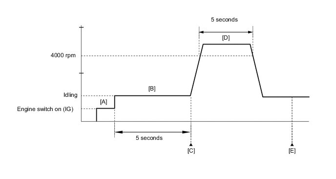
Turn the engine switch on (IG) [A].
-
Turn the GTS on.
-
Start the engine.
-
Idle the engine for 5 seconds [B].
-
Enter the following menus: Powertrain / Engine / Trouble Codes [C].
-
Read the pending DTCs.
Tech Tips
-
If a pending DTC is output, the system is malfunctioning.
-
If a pending DTC is not output, perform the following procedure.
-
-
Run the engine at an engine speed of 4000 rpm or higher for 5 seconds [D].
-
Enter the following menus: Powertrain / Engine / Trouble Codes [E].
-
Read the pending DTCs.
Tech Tips
-
If a pending DTC is output, the system is malfunctioning.
-
If a pending DTC is not output, perform the following procedure.
-
-
Enter the following menus: Powertrain / Engine / Utility / All Readiness.
-
Input the DTC: P010014 or P010016.
-
Check the DTC judgment result.
GTS Display Description NORMAL
-
DTC judgment completed
-
System normal
ABNORMAL
-
DTC judgment completed
-
System abnormal
INCOMPLETE
-
DTC judgment not completed
-
Perform driving pattern after confirming DTC enabling conditions
Tech Tips
-
If the judgment result shows NORMAL, the system is normal.
-
If the judgment result shows ABNORMAL, the system has a malfunction.
-
If the judgment result shows INCOMPLETE, perform steps [B] through [E] again.
-
CAUTION / NOTICE / HINT
Note
Inspect the fuses for circuits related to this system before performing the following procedure.
Tech Tips
Read freeze frame data using the GTS. The ECM records vehicle and driving condition information as freeze frame data the moment a DTC is stored. When troubleshooting, freeze frame data can help determine if the vehicle was moving or stationary, if the engine was warmed up or not, if the air fuel ratio was lean or rich, and other data from the time the malfunction occurred.
PROCEDURE
-
CHECK TERMINAL VOLTAGE (POWER SOURCE OF MASS AIR FLOW METER SUB-ASSEMBLY)
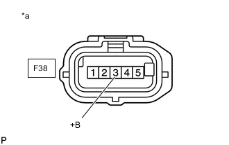
*a Front view of wire harness connector
(to Mass Air Flow Meter Sub-assembly)
-
Disconnect the mass air flow meter sub-assembly connector.
-
Turn the engine switch on (IG).
-
Measure the voltage according to the value(s) in the table below.
Standard Voltage Tester Connection Condition Specified Condition F38-3 (+B) - Body ground Engine switch on (IG) 11 to 14 V Result Proceed to OK NG
NG 
CHECK HARNESS AND CONNECTOR (SEMICONDUCTOR POWER INTEGRATION ECU - MASS AIR FLOW METER SUB-ASSEMBLY) Click here
OK 
-
-
CHECK HARNESS AND CONNECTOR (MASS AIR FLOW METER SUB-ASSEMBLY - ECM)
-
Disconnect the mass air flow meter sub-assembly connector.
-
Disconnect the ECM connector.
-
Measure the resistance according to the value(s) in the table below.
Standard Resistance Tester Connection Condition Specified Condition F38-5 (VG) - F87-116 (VG) Always Below 1 Ω F38-5 (VG) or F87-116 (VG) - Body ground and other terminals Always 10 kΩ or higher Result Proceed to OK NG
NG 
REPAIR OR REPLACE HARNESS OR CONNECTOR
OK
-
-
INSPECT MASS AIR FLOW METER SUB-ASSEMBLY
-
Inspect the mass air flow meter sub-assembly, referring to On-vehicle Inspection for Mass Air Flow Meter.
-
Inspect the mass air flow meter sub-assembly, referring to Inspection for Mass Air Flow Meter.
-
Inspect the function of the mass air flow meter sub-assembly.
-
Connect the GTS to the DLC3.
-
Turn the engine switch on (IG).
-
Turn the GTS on.
-
Enter the following menus: Powertrain / Engine / Data List / Mass Air Flow Sensor.
Powertrain > Engine > Data ListTester Display Mass Air Flow Sensor -
Start the engine.
-
Check that the Mass Air Flow Sensor value changes when the engine is raced.
OK The reading changes.
Tech Tips
Perform "Inspection After Repair" after replacing the mass air flow meter sub-assembly.
Result Proceed to OK NG -
OK
REPLACE ECM Click here
NG
REPLACE MASS AIR FLOW METER SUB-ASSEMBLY Click here
-
-
CHECK HARNESS AND CONNECTOR (SEMICONDUCTOR POWER INTEGRATION ECU - MASS AIR FLOW METER SUB-ASSEMBLY)
-
Disconnect the semiconductor power integration ECU connector.
-
Disconnect the mass air flow meter sub-assembly connector.
-
Measure the resistance according to the value(s) in the table below.
Standard Resistance Tester Connection Condition Specified Condition 2G-2 - F38-3 (+B) Always Below 1 Ω 2G-2 or F38-3 (+B) - Body ground and other terminals Always 10 kΩ or higher Result Proceed to OK NG
OK
REPLACE SEMICONDUCTOR POWER INTEGRATION ECU Click here
NG
REPAIR OR REPLACE HARNESS OR CONNECTOR
-