SFI SYSTEM(w/ Canister Pump Module), Diagnostic DTC:P25B372
| DTC Code | DTC Name |
|---|---|
| P25B372 | Turbocharger/Supercharger Wastegate "A" Actuator Stuck Open |
DESCRIPTION
Refer to DTC P024313.
| DTC No. | Detection Item | DTC Detection Condition | Trouble Area | MIL | Memory | Note |
|---|---|---|---|---|---|---|
| P25B372 | Turbocharger/Supercharger Wastegate "A" Actuator Stuck Open | The boost pressure does not increase despite control to close the waste gate valve (2 trip detection logic). |
|
Comes on | DTC stored | SAE Code: P25B3 |
MONITOR DESCRIPTION
If the boost pressure does not increase despite control to close the waste gate valve, it is determined that there is a waste gate valve stuck open malfunction. The ECM illuminates the MIL and stores this DTC.
MONITOR STRATEGY
| Required Sensors/Components | No. 2 turbo pressure sensor Mass air flow meter sub-assembly |
| Frequency of Operation | Once per driving cycle |
CONFIRMATION DRIVING PATTERN
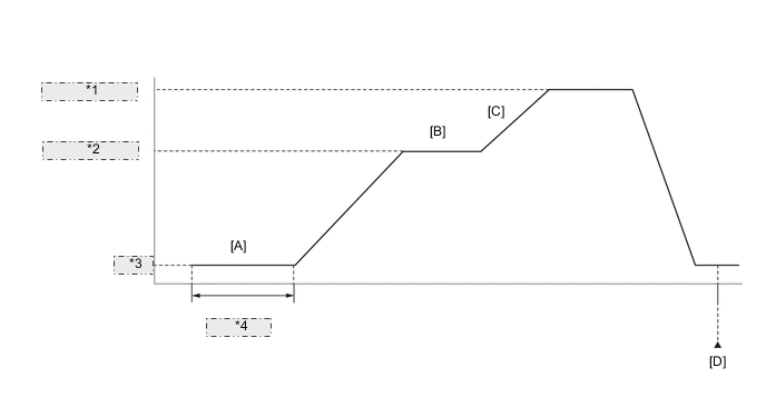
| *1 | 80 km/h or more |
| *2 | 70 km/h or more |
| *3 | Idling |
| *4 | Warming up |
-
Connect the GTS to the DLC3.
-
Turn the engine switch on (IG) and turn the GTS on.
-
Clear the DTCs (even if no DTCs are stored, perform the clear DTC procedure).
-
Turn the engine switch off and wait for at least 30 seconds.
-
Turn the engine switch on (IG) and turn the GTS on.
-
Start the engine and warm it up until the engine coolant temperature reaches 75°C (167°F) or higher [A].
-
Drive the vehicle at 70 km/h (43 mph) or more [B].
CAUTION:
When performing the confirmation driving pattern, obey all speed limits and traffic laws.
-
Accelerate to 80 km/h (50 mph) or more with the accelerator pedal fully depressed [C].
CAUTION:
When performing the confirmation driving pattern, obey all speed limits and traffic laws.
-
Enter the following menus: Powertrain / Engine / Trouble Codes [D].
-
Read the pending DTCs.
Tech Tips
-
If a pending DTC is output, the system is malfunctioning.
-
If a pending DTC is not output, perform the following procedure.
-
-
Enter the following menus: Powertrain / Engine / Utility / All Readiness.
-
Input the DTC: P25B372.
-
Check the DTC judgment result.
GTS Display Description NORMAL
-
DTC judgment completed
-
System normal
ABNORMAL
-
DTC judgment completed
-
System abnormal
INCOMPLETE
-
DTC judgment not completed
-
Perform driving pattern after confirming DTC enabling conditions
N/A
-
Unable to perform DTC judgment
-
Number of DTCs which do not fulfill DTC preconditions has reached ECU memory limit
Tech Tips
-
If the judgment result shows NORMAL, the system is normal.
-
If the judgment result shows ABNORMAL, the system has a malfunction.
-
If the judgment result shows INCOMPLETE or N/A, perform steps [B] through [D] again.
-
WIRING DIAGRAM
-
Refer to DTC P010012 for the mass air flow meter sub-assembly circuit.
-
Refer to DTC P023511 for No. 2 turbo pressure sensor circuit.
CAUTION / NOTICE / HINT
Tech Tips
Read freeze frame data using the GTS. The ECM records vehicle and driving condition information as freeze frame data the moment a DTC is stored. When troubleshooting, freeze frame data can help determine if the vehicle was moving or stationary, if the engine was warmed up or not, if the air fuel ratio was lean or rich, and other data from the time the malfunction occurred.
PROCEDURE
-
CHECK ANY OTHER DTCS OUTPUT (IN ADDITION TO DTC P25B372)
-
Connect the GTS to the DLC3.
-
Turn the engine switch on (IG).
-
Turn the GTS on.
-
Enter the following menus: Powertrain / Engine / Trouble Codes.
-
Read the DTCs.
Powertrain > Engine > Trouble CodesResult Result Proceed to DTC P25B372 is output A DTC P25B372 and other DTCs are output B Tech Tips
If any DTCs other than P25B372 are output, troubleshoot those DTCs first.
B 
GO TO DTC CHART Click here
A 
-
-
PERFORM ACTIVE TEST USING GTS (CONTROL THE WASTEGATE VALVE DUTY RATIO)
-
Connect the GTS to the DLC3.
-
Start the engine.
-
Turn the GTS on.
-
Enter the following menus: Powertrain / Engine / Active Test / Control the Wastegate Valve Duty Ratio.
Powertrain > Engine > Active TestTester Display Control the Wastegate Valve Duty Ratio -
Perform the Active Test. Check that the waste gate valve is operating.
OK The waste gate valve is operating. Result Proceed to OK NG
NG 
PERFORM ACTIVE TEST USING GTS (CONTROL THE WASTEGATE VALVE DUTY RATIO) Click here
OK
-
-
INSPECT AIR BY-PASS VALVE ASSEMBLY
-
Inspect the air by-pass valve assembly, referring to On-vehicle Inspection for Air by-pass Valve Assembly.
-
Inspect the air by-pass valve assembly, referring to Inspection for Air by-pass Valve Assembly.
Result Proceed to OK NG
NG
REPLACE AIR BY-PASS VALVE ASSEMBLY Click here
OK
-
-
INSPECT MASS AIR FLOW METER SUB-ASSEMBLY
-
Inspect the mass air flow meter sub-assembly, referring to On-vehicle Inspection for Mass Air Flow Meter.
-
Inspect the mass air flow meter sub-assembly, referring to Inspection for Mass Air Flow Meter.
-
Inspect the operation of the mass air flow meter sub-assembly.
-
Connect the GTS to the DLC3.
-
Start the engine.
-
Turn the GTS on.
-
Enter the following menus: Powertrain / Engine / Data List / Engine Speed, Mass Air Flow Sensor and Coolant Temperature.
Powertrain > Engine > Data ListTester Display Engine Speed Mass Air Flow Sensor Coolant Temperature -
Allow the engine to idle until Coolant Temperature reaches 75°C (167°F) or higher.
-
Read Mass Air Flow Sensor while maintaining an engine speed of 3000 rpm.
Standard GTS Display Condition Specified Condition Mass Air Flow Sensor Engine warmed up
Shift lever position: P
A/C: Off
Engine Speed: 3000 rpm
Between 6.0 gm/sec and 18.0 gm/sec
Result Proceed to OK NG -
NG
CHECK TERMINAL VOLTAGE (POWER SOURCE OF MASS AIR FLOW METER SUB-ASSEMBLY) Click here
OK
-
-
INSPECT NO. 2 TURBO PRESSURE SENSOR
-
Inspect the No. 2 turbo pressure sensor.
Result Proceed to OK NG
NG
CHECK TERMINAL VOLTAGE (POWER SOURCE OF NO. 2 TURBO PRESSURE SENSOR) Click here
OK
-
-
CHECK WHETHER DTC OUTPUT RECURS (DTC P25B372)
-
Connect the GTS to the DLC3.
-
Turn the engine switch on (IG).
-
Turn the GTS on.
-
Clear the DTCs.
Powertrain > Engine > Clear DTCs -
Turn the engine switch off and wait for at least 30 seconds.
-
Start the engine and warm it up.
-
Turn the GTS on.
-
Drive the vehicle in accordance with the driving pattern described in Confirmation Driving Pattern.
-
Enter the following menus: Powertrain / Engine / Utility / All Readiness.
Powertrain > Engine > UtilityTester Display All Readiness -
Input the DTC: P25B372.
-
Check the DTC judgment result.
Result Result Proceed to NORMAL
(DTCs are not output)
A ABNORMAL
(DTC P25B372 is output)
B
A
CHECK FOR INTERMITTENT PROBLEMS Click here
B
-
-
REPLACE ECM
-
Replace the ECM.
Result Proceed to NEXT
NEXT
GO TO STEP 31 Click here
-
-
CHECK TERMINAL VOLTAGE (POWER SOURCE OF NO. 2 TURBO PRESSURE SENSOR)
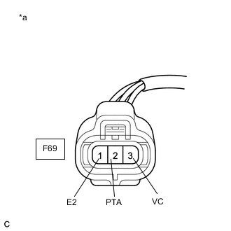
*a Front view of wire harness connector
(to No. 2 Turbo Pressure Sensor)
-
Disconnect the No. 2 turbo pressure sensor connector.
-
Turn the engine switch on (IG).
-
Measure the voltage according to the value(s) in the table below.
Standard Voltage Tester Connection Condition Specified Condition F69-3 (VC) - F69-1 (E2) Engine switch on (IG) 4.75 to 5.25 V F69-2 (PTA) - F69-1 (E2) Engine switch on (IG) 3.0 to 5.25 V Result Proceed to OK NG
NG
CHECK HARNESS AND CONNECTOR (NO. 2 TURBO PRESSURE SENSOR - ECM) Click here
OK
-
-
REPLACE NO. 2 TURBO PRESSURE SENSOR
-
Replace the No. 2 turbo pressure sensor.
Result Proceed to NEXT
NEXT
GO TO STEP 31 Click here
-
-
CHECK HARNESS AND CONNECTOR (NO. 2 TURBO PRESSURE SENSOR - ECM)
-
Disconnect the No. 2 turbo pressure sensor connector.
-
Disconnect the ECM connector.
-
Measure the resistance according to the value(s) in the table below.
Standard Resistance Tester Connection Condition Specified Condition F69-3 (VC) - F66-140 (VPTA) Always Below 1 Ω F69-2 (PTA) - F66-108 (PTA) Always Below 1 Ω F69-1 (E2) - F66-139 (EPTA) Always Below 1 Ω F69-3 (VC) or F66-140 (VPTA) - Body ground and other terminals Always 10 kΩ or higher F69-2 (PTA) or F66-108 (PTA) - Body ground and other terminals Always 10 kΩ or higher Result Proceed to OK NG
NG
REPAIR OR REPLACE HARNESS OR CONNECTOR Click here
OK
-
-
REPLACE ECM
-
Replace the ECM.
Result Proceed to NEXT
NEXT
GO TO STEP 31 Click here
-
-
REPAIR OR REPLACE HARNESS OR CONNECTOR
-
Repair or replace the wire harness or connector.
Result Proceed to NEXT
NEXT
GO TO STEP 31 Click here
-
-
CHECK TERMINAL VOLTAGE (POWER SOURCE OF MASS AIR FLOW METER SUB-ASSEMBLY)
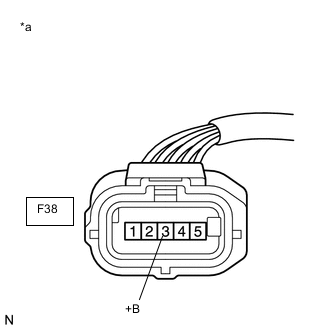
*a Front view of wire harness connector
(to Mass Air Flow Meter Sub-assembly)
-
Disconnect the mass air flow meter sub-assembly connector.
-
Turn the engine switch on (IG).
-
Measure the voltage according to the value(s) in the table below.
Standard Voltage Tester Connection Condition Specified Condition F38-3 (+B) - Body ground Engine switch on (IG) 11 to 14 V Result Proceed to OK NG
NG
CHECK HARNESS AND CONNECTOR (SEMICONDUCTOR PWR INTEGRATION ECU - MASS AIR FLOW METER SUB-ASSEMBLY) Click here
OK
-
-
CHECK HARNESS AND CONNECTOR (MASS AIR FLOW METER SUB-ASSEMBLY - ECM)
-
Disconnect the mass air flow meter sub-assembly connector.
-
Disconnect the ECM connector.
-
Measure the resistance according to the value(s) in the table below.
Standard Resistance Tester Connection Condition Specified Condition F38-5 (VG) - F66-92 (VG) Always Below 1 Ω F38-4 (E2G) - F66-91 (E2G) Always Below 1 Ω F38-5 (VG) or F66-92 (VG) - Body ground and other terminals Always 10 kΩ or higher Result Proceed to OK NG
NG
GO TO STEP 19 Click here
OK
-
-
REPLACE MASS AIR FLOW METER SUB-ASSEMBLY
-
Replace the mass air flow meter sub-assembly.
Tech Tips
Perform "Inspection After Repair" after replacing the mass air flow meter sub-assembly.
Result Proceed to NEXT
NEXT
GO TO STEP 31 Click here
-
-
CHECK HARNESS AND CONNECTOR (SEMICONDUCTOR PWR INTEGRATION ECU - MASS AIR FLOW METER SUB-ASSEMBLY)
-
Disconnect the semiconductor pwr integration ECU connector.
-
Disconnect the mass air flow meter sub-assembly connector.
-
Measure the resistance according to the value(s) in the table below.
Standard Resistance Tester Connection Condition Specified Condition 2G-1 - F38-3 (+B) Always Below 1 Ω 2G-1 or F38-3 (+B) - Body ground and other terminals Always 10 kΩ or higher Result Proceed to OK NG
NG
REPAIR OR REPLACE HARNESS OR CONNECTOR Click here
OK
-
-
REPLACE SEMICONDUCTOR POWER INTEGRATION ECU
-
Replace the semiconductor pwr integration ECU.
Result Proceed to NEXT
NEXT
GO TO STEP 31 Click here
-
-
REPLACE AIR BY-PASS VALVE ASSEMBLY
-
Replace the air by-pass valve assembly.
Result Proceed to NEXT
NEXT
GO TO STEP 31 Click here
-
-
REPAIR OR REPLACE HARNESS OR CONNECTOR
-
Repair or replace the wire harness or connector.
Result Proceed to NEXT
NEXT
GO TO STEP 31 Click here
-
-
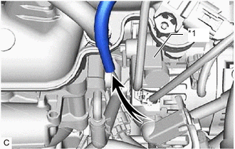
PERFORM ACTIVE TEST USING GTS (CONTROL THE WASTEGATE VALVE DUTY RATIO)
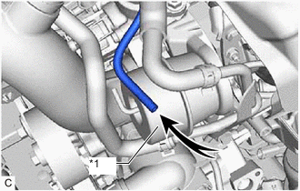
*1 Waste Gate Valve Actuator with Bracket Assembly
-
Disconnect the vacuum hose of the waste gate valve actuator with bracket assembly.
-
Connect the GTS to the DLC3.
-
Start the engine.
-
Turn the GTS on.
-
Enter the following menus: Powertrain / Engine / Active Test / Control the Wastegate Valve Duty Ratio.
Powertrain > Engine > Active TestTester Display Control the Wastegate Valve Duty Ratio -
When the waste gate valve is operated using the GTS, check whether the vacuum hose of the waste gate valve actuator with bracket assembly applies suction your finger.
OK GTS Operation Specified Condition 100% Vacuum hose applies suction to finger 0% Vacuum hose applies no suction to finger Result Proceed to OK NG
NG
CHECK VACUUM PUMP ASSEMBLY Click here
OK
-
-
INSPECT WASTE GATE VALVE ACTUATOR WITH BRACKET ASSEMBLY AND WASTE GATE VALVE (TURBINE HOUSING WITH VALVE SUB-ASSEMBLY)
-
Inspect the waste gate valve actuator with bracket assembly.
-
Inspect the waste gate valve.
Result Result Proceed to Waste gate valve actuator with bracket assembly is abnormal A Waste gate valve is abnormal B
B
REPLACE TURBINE HOUSING WITH VALVE SUB-ASSEMBLY Click here
A
-
-
REPLACE WASTE GATE VALVE ACTUATOR WITH BRACKET ASSEMBLY
-
Replace the waste gate valve actuator with bracket assembly.
Result Proceed to NEXT
NEXT
GO TO STEP 31 Click here
-
-
REPLACE TURBINE HOUSING WITH VALVE SUB-ASSEMBLY
-
Replace the turbine housing with valve sub-assembly.
Result Proceed to NEXT
NEXT
GO TO STEP 31 Click here
-
-
CHECK VACUUM PUMP ASSEMBLY
*1 Vacuum Regulating Valve Assembly
-
Disconnect the vacuum hose (vacuum pump assembly side) of the vacuum regulating valve assembly.
-
Start the engine.
-
Check whether the vacuum hose of the vacuum regulating valve assembly applies suction your finger.
OK Vacuum hose applies suction to finger. Result Proceed to OK NG
NG
INSPECT VACUUM PUMP ASSEMBLY Click here
OK
-
-
INSPECT VACUUM REGULATING VALVE ASSEMBLY
-
Inspect the vacuum regulating valve assembly.
Result Proceed to OK NG
NG
REPLACE VACUUM REGULATING VALVE ASSEMBLY Click here
OK
-
-
REPAIR OR REPLACE VACUUM HOSE (WASTE GATE VALVE ACTUATOR WITH BRACKET ASSEMBLY - VACUUM REGULATING VALVE ASSEMBLY)
-
repair or replace the vacuum hose (waste gate valve actuator with bracket assembly - vacuum regulating valve assembly)
Result Proceed to NEXT
NEXT
GO TO STEP 31 Click here
-
-
REPLACE VACUUM REGULATING VALVE ASSEMBLY
-
Replace the vacuum regulating valve assembly.
Result Proceed to NEXT
NEXT
GO TO STEP 31 Click here
-
-
INSPECT VACUUM PUMP ASSEMBLY
-
Inspect the vacuum pump assembly.
Result Proceed to OK NG
NG
REPLACE VACUUM PUMP ASSEMBLY Click here
OK
-
-
REPAIR OR REPLACE VACUUM LINE (VACUUM REGULATING VALVE ASSEMBLY - VACUUM PUMP ASSEMBLY)
-
repair or replace the vacuum line (vacuum regulating valve assembly - vacuum pump assembly).
Result Proceed to NEXT
NEXT
GO TO STEP 31 Click here
-
-
REPLACE VACUUM PUMP ASSEMBLY
-
Replace the vacuum pump assembly.
Result Proceed to NEXT
NEXT
-
-
CHECK WHETHER DTC OUTPUT RECURS (DTC P25B372)
-
Connect the GTS to the DLC3.
-
Turn the engine switch on (IG).
-
Turn the GTS on.
-
Clear the DTCs.
Powertrain > Engine > Clear DTCs -
Turn the engine switch off and wait for at least 30 seconds.
-
Start the engine and warm it up.
-
Turn the GTS on.
-
Drive the vehicle in accordance with the driving pattern described in Confirmation Driving Pattern.
-
Enter the following menus: Powertrain / Engine / Utility / All Readiness.
Powertrain > Engine > UtilityTester Display All Readiness -
Input the DTC: P25B372.
-
Check the DTC judgment result.
GTS Display Description NORMAL
-
DTC judgment completed
-
System normal
ABNORMAL
-
DTC judgment completed
-
System abnormal
INCOMPLETE
-
DTC judgment not completed
-
Perform driving pattern after confirming DTC enabling conditions
N/A
-
Unable to perform DTC judgment
-
Number of DTCs which do not fulfill DTC preconditions has reached ECU memory limit
Result Proceed to NEXT -
NEXT
END
-