AUDIO AND VISUAL SYSTEM(for 7 Inch Display), Diagnostic DTC:B1575
| DTC Code | DTC Name |
|---|---|
| B1575 | GVIF Disconnected (from EMV/MM Integrated Device to Multi Display) |
DESCRIPTION
The radio receiver assembly and multi-display assembly are connected via video signal (digital) lines.
This DTC is stored when a video signal (digital) line is disconnected.
| DTC No. | Detection Item | DTC Detection Condition | Trouble Area |
|---|---|---|---|
| B1575 | GVIF Disconnected (from EMV/MM Integrated Device to Multi Display) | GVIF disconnected (from radio receiver assembly to multi-display assembly) |
|
WIRING DIAGRAM
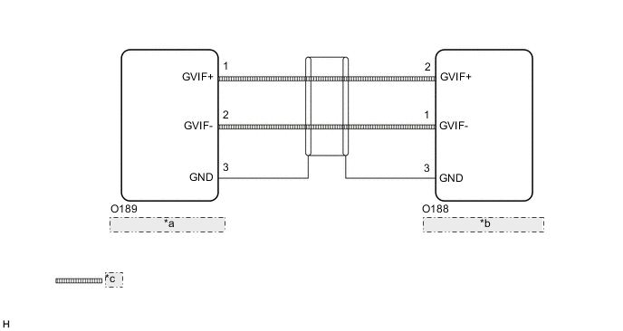
| *a | Multi-display Assembly |
| *b | Radio Receiver Assembly |
| *c | GVIF Cable |
CAUTION / NOTICE / HINT
Note
-
Depending on the parts that are replaced during vehicle inspection or maintenance, performing initialization, registration or calibration may be needed. Refer to Precaution for Audio and Visual System.
-
When replacing the radio receiver assembly, always replace it with a new one.
If a radio receiver assembly which was installed to another vehicle is used, the following may occur:
-
A communication malfunction DTC may be stored.
-
The radio receiver assembly may not operate normally.
PROCEDURE
-
CHECK DTC
-
Clear the DTCs.
Body Electrical > Navigation System > Clear DTCs -
Turn the engine switch off.
-
Recheck for DTCs and check that no DTCs are output.
Body Electrical > Navigation System > Trouble CodesOK No DTCs are output. Result Proceed to OK NG
OK 
USE SIMULATION METHOD TO CHECK Click here
NG 
-
-
CHECK HARNESS AND CONNECTOR (MULTI-DISPLAY ASSEMBLY - RADIO RECEIVER ASSEMBLY)
-
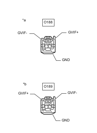
*a Front view of wire harness connector
(to Radio Receiver Assembly)
*b Front view of wire harness connector
(to Multi-display Assembly)
Disconnect the O189 multi-display assembly connector.
-
Disconnect the O188 radio receiver assembly connector.
-
Measure the resistance according to the value(s) in the table below.
Standard Resistance Tester Connection Condition Specified Condition O188-2 (GVIF+) - O189-1 (GVIF+) Always Below 1 Ω O188-1 (GVIF-) - O189-2 (GVIF-) Always Below 1 Ω O188-3 (GND) - O189-3 (GND) Always Below 1 Ω O188-2 (GVIF+) or O189-1 (GVIF+) - Body ground Always 10 kΩ or higher O188-1 (GVIF-) or O189-2 (GVIF-) - Body ground Always 10 kΩ or higher O188-3 (GND) or O189-3 (GND) - Body ground Always 10 kΩ or higher Result Proceed to OK NG
NG
REPAIR OR REPLACE HARNESS OR CONNECTOR
OK
-
-
CHECK MULTI-DISPLAY ASSEMBLY
-
Replace the multi-display assembly with a new or known good one.
-
Clear the DTCs.
Body Electrical > Navigation System > Clear DTCs -
Turn the engine switch off.
-
Recheck for DTCs and check that no DTCs are output.
Body Electrical > Navigation System > Trouble CodesOK No DTCs are output. Result Proceed to OK NG
OK
END (MULTI-DISPLAY ASSEMBLY IS DEFECTIVE)
NG
REPLACE RADIO RECEIVER ASSEMBLY Click here
-