STEERING LINKAGE INSPECTION

PROCEDURE
-
INSPECT TOTAL PRELOAD
Note
Inspect the total preload in a no-load condition by removing the tie rod assembly RH, tie rod assembly LH and steering rack boots.
-
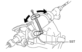
Install SST to the pinion shaft and turn it left and right 5 times or more.
- SST
- 09616-00011
-
Using SST and a torque wrench, turn the pinion shaft continuously at a rate of 4 to 6 seconds per turn to check the total preload of the power steering link assembly.
Standard Preload 1.5 to 2.46 N*m (16 to 25 kgf*cm, 14 to 21 in.*lbf) Note
Check the total preload around the steering rack center position.
If the total preload is not within the specified range, replace the power steering link assembly with a new one.
-
-
INSPECT POWER STEERING LINK ASSEMBLY
-
Disconnect the C1 power steering motor connector.
-
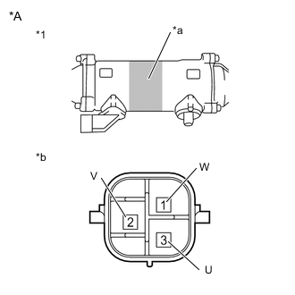
*A for LHD *1 Power Steering Link Assembly *a Area to Set Negative Probe *b Component without harness connected
(Power Steering Motor)
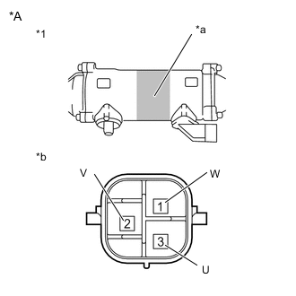
*A for RHD *1 Power Steering Link Assembly *a Area to Set Negative Probe *b Component without harness connected
(Power Steering Motor)
Measure the resistance according to the value(s) in the table below.
Standard Resistance Tester Connection Condition Specified Condition 1 (W) - 3 (U) Always 0.07 to 10 Ω 2 (V) - 1 (W) Always 0.07 to 10 Ω 3 (U) - 2 (V) Always 0.07 to 10 Ω 1 (W) - Power steering link housing* Always 100 kΩ or higher 2 (V) - Power steering link housing* Always 100 kΩ or higher 3 (U) - Power steering link housing* Always 100 kΩ or higher *: Touch the negative probe to the power steering link assembly housing at the position shown in the illustration to perform the measurement.
-
Disconnect the C3 torque sensor connector.
-
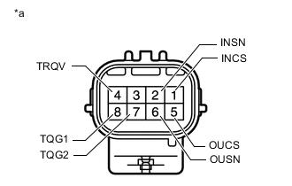
*a Component without harness connected
(Torque Sensor)
Measure the resistance according to the value(s) in the table below.
Standard Resistance Tester Connection Condition Specified Condition 1 (INCS) - 7 (TQG2) Always 90 to 170 Ω 2 (INSN) - 7 (TQG2) Always 300 to 430 Ω 4 (TRQV) - 8 (TQG1) Always 4 to 14 Ω 5 (OUCS) - 7 (TQG2) Always 90 to 170 Ω 6 (OUSN) - 7 (TQG2) Always 300 to 430 Ω -
Disconnect the C2 motor rotation angle sensor connector.
-
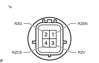
*a Component without harness connected
(Motor Rotation Angle Sensor)
Measure the resistance according to the value(s) in the table below.
Standard Resistance Tester Connection Condition Specified Condition 1 (RZSN) - 2 (RZG) Always 50 to 140 Ω 3 (RZV) - 2 (RZG) Always 15 to 45 Ω 4 (RZCS) - 2 (RZG) Always 50 to 140 Ω
-