STEERING COLUMN ASSEMBLY REMOVAL
PROCEDURE
-
PRECAUTION
-
CHANGE POWER TILT AND POWER TELESCOPIC STEERING COLUMN SYSTEM SETTINGS (for Power Tilt and Power Telescopic Steering Column)
-
Disable the auto tilt away function by changing the customize settings.
Note
Record the current customize setting (whether the auto tilt away function is enabled or disabled) in order to restore the current setting after finishing the operation.
Tech Tips
Performing the above operation causes the auto tilt away function to be disabled when the engine switch is turned off.
-
Turn the engine switch on (IG). Operate the tilt and telescopic switch to fully extend and lower the steering column assembly.
-
-
ALIGN FRONT WHEELS FACING STRAIGHT AHEAD
-
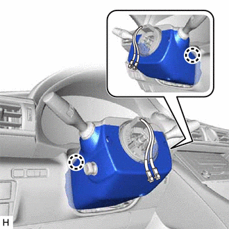
REMOVE HORN BUTTON ASSEMBLY
-
REMOVE STEERING WHEEL ASSEMBLY
-
REMOVE STEERING COLUMN COVER
-
for Manual Tilt and Manual Telescopic Steering Column:
-
Remove the 2 screws.
-
Disengage the 2 claws.
-
Disengage the claw and remove the steering column cover (lower).
-
-
for Power Tilt and Power Telescopic Steering Column:
-
Remove the 3 screws.
-
Disengage the 2 claws and remove the steering column cover (lower).
-
-
Disengage the 6 clips from the steering column cover (upper).
-
Disengage the 2 claws and remove the steering column cover (upper).
-
-
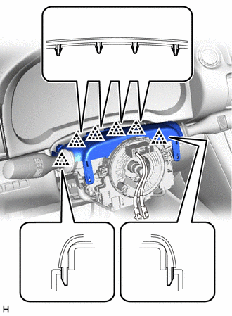
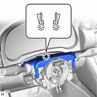
REMOVE TURN SIGNAL SWITCH ASSEMBLY WITH SPIRAL CABLE SUB-ASSEMBLY
Note
-
Do not replace the spiral cable with sensor sub-assembly with the battery connected and the engine switch on (IG).
-
Do not rotate the spiral cable with sensor sub-assembly without the steering wheel assembly installed, with the battery connected and the engine switch on (IG).
-
Ensure that the steering wheel assembly is installed and aligned straight when inspecting the steering sensor.
-
Disconnect each connector from the turn signal switch assembly with spiral cable sub-assembly.
-
Disengage the 3 claws to remove the turn signal switch assembly with spiral cable sub-assembly from the steering column assembly.
-
-
REMOVE LOWER NO. 1 INSTRUMENT PANEL AIRBAG ASSEMBLY
-
REMOVE NO. 1 AIR DUCT SUB-ASSEMBLY (for LHD)
-
Remove the bolt and No. 1 air duct sub-assembly.
-
-
REMOVE NO. 2 AIR DUCT SUB-ASSEMBLY (for RHD)
Tech Tips
Use the same procedure as for the No. 1 air duct sub-assembly.
-
REMOVE STEERING COLUMN ASSEMBLY
-
w/o VGRS:
-
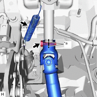
*a Matchmark Put matchmarks on the No. 2 steering intermediate shaft assembly and steering column assembly.
-
Remove the bolt.
-
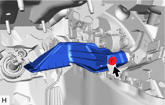
Remove the brake pedal return spring from the steering column assembly and push rod pin.
-
-
w/ VGRS:
-
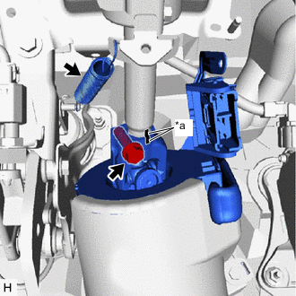
*a Matchmark Put matchmarks on the steering actuator assembly and steering column assembly.
-
Remove the bolt.
-
Remove the brake pedal return spring from the steering column assembly and push rod pin.
-
-
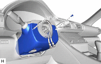
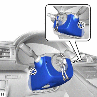
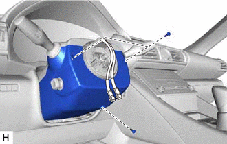
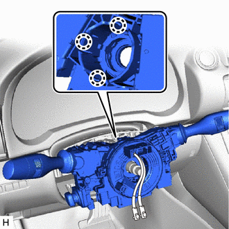
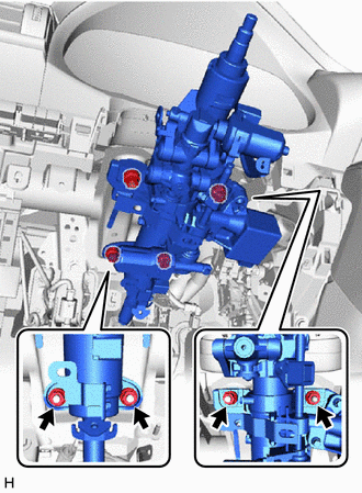
Disconnect each connector and disengage each wire harness clamp from the steering column assembly.
-
for Manual Tilt and Manual Telescopic Steering Column:
-
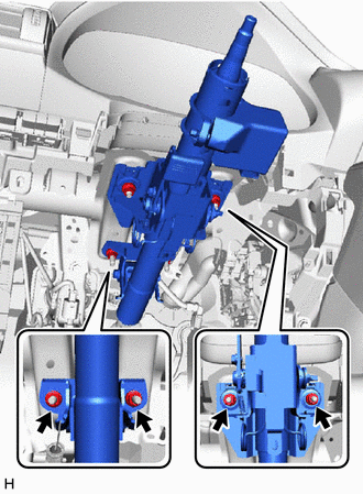
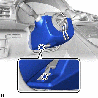
Remove the 4 nuts and steering column assembly.
-
-
for Power Tilt and Power Telescopic Steering Column:
-
Remove the 4 nuts and steering column assembly.
-
-
w/o VGRS:
-
Separate the steering column assembly from the No. 2 steering intermediate shaft assembly.
-
-
w/ VGRS:
-
Separate the steering column assembly from the steering actuator assembly.
-
-
-
REMOVE FRONT SUSPENSION MEMBER BRACE (w/ No. 2 Engine Under Cover)
-
REMOVE NO. 2 ENGINE UNDER COVER (w/ No. 2 Engine Under Cover)
-
REMOVE NO. 2 STEERING INTERMEDIATE SHAFT ASSEMBLY (w/o VGRS)
-
Loosen the clamp.
-
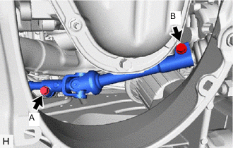
Loosen the bolt (A).
Note
Do not remove the bolt (A).
-
Remove the bolt (B).
-
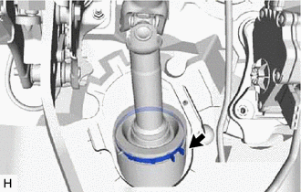
*a Matchmark Slide the steering sliding yoke sub-assembly and put matchmarks on the steering sliding yoke sub-assembly and power steering link assembly.
-
Separate the steering sliding yoke sub-assembly from the power steering link assembly.
-
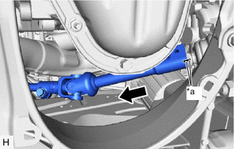
Remove the steering sliding yoke sub-assembly with the No. 2 steering intermediate shaft assembly from the vehicle.
-
-
REMOVE LOWER MAIN SHAFT DUST COVER (w/ VGRS)
-
REMOVE STEERING ACTUATOR ASSEMBLY (w/ VGRS)
-
REMOVE STEERING SLIDING YOKE SUB-ASSEMBLY
-
w/o VGRS:
-
*a Matchmark Put matchmarks on the steering sliding yoke sub-assembly and No. 2 steering intermediate shaft assembly.
-
Remove the bolt.
-
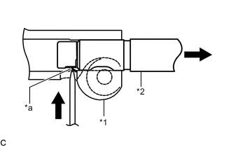
*1 Steering Sliding Yoke Sub-assembly *2 No. 2 Steering Intermediate Shaft Assembly *a Claw Using a screwdriver, disengage the claw and remove the steering sliding yoke sub-assembly from the No. 2 steering intermediate shaft assembly.
Tech Tips
Even if the claw is broken, the No. 2 steering intermediate shaft assembly can be reused if the claw is removed.
-
-
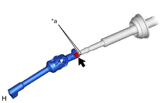
w/ VGRS:
-
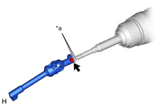
*a Matchmark Put matchmarks on the steering sliding yoke sub-assembly and steering actuator assembly.
-
Remove the bolt and steering sliding yoke sub-assembly.
-
-