DYNAMIC REAR STEERING ACTUATOR REMOVAL

PROCEDURE
-
PRECAUTION
-
DISCONNECT CABLE FROM NEGATIVE BATTERY TERMINAL
-
REMOVE REAR WHEELS
-
REMOVE NO. 1 FLOOR UNDER COVER ASSEMBLY
-
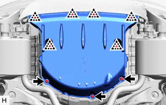
Disconnect the 3 grommets and remove the 6 clips and No. 1 floor under cover assembly.
-
-
REMOVE TAIL EXHAUST PIPE LH
-
DISCONNECT REAR STEERING TIE ROD ASSEMBLY LH
-
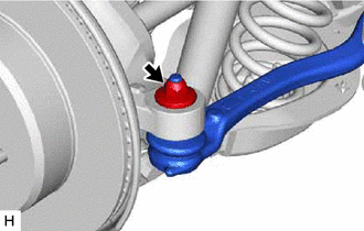
Remove the nut.
-
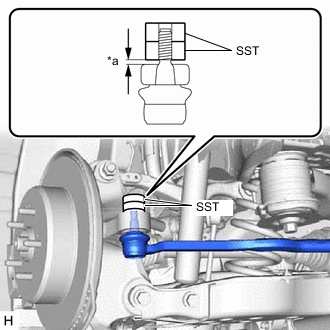
*a 1 mm (0.0394 in.) Install 2 spacers (SST spacer B) as shown in the illustration.
- SST
- 09960-20010 ( 09961-02060 )
Note
-
Be sure to install SST to prevent the spacer of the rear axle carrier sub-assembly from coming off.
-
Make sure that the clearance between the rear axle assembly and spacers (SST spacer B) is 1 mm (0.0394 in.) or more to prevent damage to SST.
-
Using SST, separate the rear steering tie rod assembly LH from the rear axle carrier sub-assembly as shown in the illustration.
- SST
- 09960-20010 ( 09961-02010 )
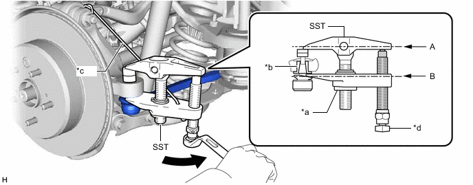
*a Nut *b Spacer *c Tie string without any slack *d Place wrench here 
Turn 
Molybdenum Grease CAUTION:
Apply molybdenum grease to the threads and the tip of the SST bolt.
Note
-
Install SST so that (A) and (B) shown in the illustration are parallel. Otherwise, the ball joint dust cover may be damaged.
-
Be sure to place the wrench on the part shown in the illustration.
-
Be sure to tighten the string firmly to secure SST to the rear upper control arm assembly to prevent SST from falling off.
-
Make sure that SST is securely positioned on the spacer.
-
Do not damage the rear steering tie rod assembly LH ball joint dust cover.
-
If the spacer has come off, replace the rear axle carrier sub-assembly and rear steering link assembly with a new one.
-
-
DISCONNECT REAR STEERING TIE ROD ASSEMBLY RH
Tech Tips
Perform the same procedure as for the LH side.
-
REMOVE NO. 1 LUGGAGE COMPARTMENT TRIM COVER
-
REMOVE SPARE WHEEL COVER TRAY
-
REMOVE REAR LUGGAGE COMPARTMENT TRIM COVER
-
REMOVE FRONT LUGGAGE COMPARTMENT TRIM COVER
-
REMOVE NO. 1 LUGGAGE COMPARTMENT LIGHT ASSEMBLY
-
REMOVE FRONT UPPER LUGGAGE COMPARTMENT TRIM COVER
-
SEPARATE LUGGAGE COMPARTMENT TRIM COVER LH
-
REMOVE REAR STEERING LINK ASSEMBLY
-
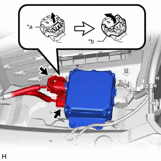
*a Lock of the Lock Lever *b Lock Lever Disconnect the 2 connectors from the rear steering control ECU.
Tech Tips
When disconnecting the connector with lock lever, pull out the lock of the lock lever and turn the lock lever as shown in the illustration.
-
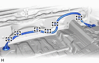
Disengage the 6 wire harness clamps.
-
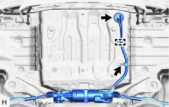
Remove the nut.
-
Disengage the wire harness clamp and disconnect the grommet.
-
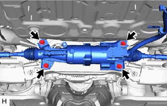
Remove the 4 bolts and rear steering link assembly.
Note
Do not drop the rear steering link assembly.
-