DYNAMIC REAR STEERING SYSTEM, Diagnostic DTC:C1B14/24, C1B24/34
| DTC Code | DTC Name |
|---|---|
| C1B14/24 | Stroke Sensor Circuit |
| C1B24/34 | Stroke Sensor(Actuator Angle Indeterminate) |
DESCRIPTION
When the DRS ECU (rear steering control ECU) detects a problem with the stroke sensor circuit, DTC C1B14/24 and C1B24/34 are stored.
| DTC No. | Detection Item | DTC Detection Condition | Trouble Area | Warning Indicate | Return-to-normal Condition |
|---|---|---|---|---|---|
| C1B14/24 | Stroke Sensor Circuit | All conditions are met for approximately 0.2 seconds or more:
|
|
Comes on | Engine switch on (IG) again |
| C1B24/34 | Stroke Sensor(Actuator Angle Indeterminate) | All conditions are met:
|
|
Comes on | Engine switch on (IG) again |
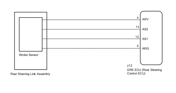
WIRING DIAGRAM
CAUTION / NOTICE / HINT
Note
-
When replacing the DRS ECU (rear steering control ECU), perform neutral position memorization and motor rotation angle sensor calibration.
-
If the rear steering link assembly or the rear suspension is removed and installed, replaced, or adjusted, after performing actuator calibration value initialization, perform neutral position memorization and motor rotation angle sensor calibration.
-
Since DTC C15C9/76 is stored in the VGRS ECU (front steering control ECU), after performing repairs on the dynamic rear steering system, clear the DTCs for the VGRS system.
PROCEDURE
-
CHECK FOR DTC
-
Check for DTCs.
Chassis > DRS > Trouble CodesResult Result Proceed to DTC C1B14/24 or C1B24/34 is output as a past DTC A DTC C1B14/24 or C1B24/34 is output as a current DTC B
B 
GO TO STEP 4 Click here
A 
-
-
PERFORM ACTUATOR FORCED ACTIVATION
-
Perform actuator forced activation.
Result Proceed to NEXT
NEXT
-
-
RECONFIRM DTC
-
Check for DTCs.
Chassis > DRS > Trouble CodesResult Result Proceed to DTC C1B14/24 or C1B24/34 is output as a current DTC A DTC C1B14/24 or C1B24/34 is output as a past DTC B
B 
USE SIMULATION METHOD TO CHECK Click here
A
-
-
INSPECT REAR STEERING LINK ASSEMBLY (STROKE SENSOR)
-
Turn the engine switch off.
-
Disconnect the z12 rear steering link assembly connector from the DRS ECU (rear steering control ECU).
-
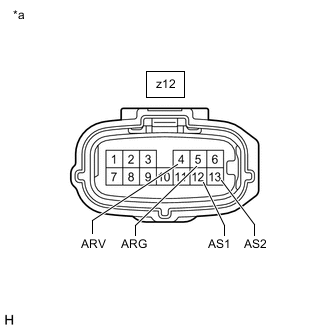
*a Front view of rear steering link assembly connector
(to DRS ECU [Rear Steering Control ECU])
Measure the resistance according to the value(s) in the table below.
Standard Resistance Tester Connection Condition Specified Condition z12-4 (ARV) - z12-5 (ARG) Always 5 to 50 Ω z12-12 (AS1) - z12-5 (ARG) Always 4 to 5 kΩ z12-13 (AS2) - z12-5 (ARG) Always 12 to 14.5 kΩ z12-4 (ARV) - z12-12 (AS1) Always 4 to 5 kΩ z12-4 (ARV) - z12-13 (AS2) Always 12 to 14.5 kΩ z12-12 (AS1) - z12-13 (AS2) Always 16 to 19 kΩ z12-4 (ARV) - Body ground Always 100 kΩ or higher z12-5 (ARG) - Body ground Always 100 kΩ or higher z12-12 (AS1) - Body ground Always 100 kΩ or higher z12-13 (AS2) - Body ground Always 100 kΩ or higher Result Proceed to OK NG
OK
REPLACE DRS ECU (REAR STEERING CONTROL ECU) Click here
NG
REPLACE REAR STEERING LINK ASSEMBLY Click here
-