NAVIGATION SYSTEM TERMINALS OF ECU
Tech Tips
Check from the rear of the connector while it is connected to the components.
-
RADIO RECEIVER ASSEMBLY
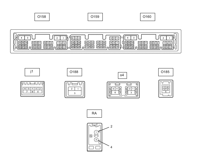
Terminal No. (Symbol) Wiring Color Terminal Description Condition Specified Condition O159-1 (VMTF) - O158-1 (GND1) W - W-B Visual mute signal Engine switch on (ACC) 3.5 V or higher → Below 1 V → 3.5 V or higher O159-5 (CNH1) BE Local bus communication signal - - O159-6 (CNL1) B Local bus communication signal - - O159-13 (CANH) BE CAN communication signal - - O159-14 (CANL) B CAN communication signal - - O159-15 (ILL+) - O158-1 (GND1) G - W-B Illumination signal Light control switch off Below 1 V Light control switch in tail or head position 11 to 14 V O159-16 (ILL-) - O158-1 (GND1) BE - W-B Illumination signal Light control switch off Below 1 V Light control switch in tail or head position Pulse generation O159-19 (IG) - O158-1 (GND1) P - W-B Power source (IG) Engine switch off Below 1 V Engine switch on (IG) 11 to 14 V O159-20 (PKB) - O158-1 (GND1) GR - W-B Parking brake signal See "Vehicle Signal Check Mode" in Operation Check
- O159-21 (MIN+) - O158-1 (GND1) W - W-B Microphone voice signal See "Microphone Check" in Operation Check
- O159-22 (MIN-) - Body ground B - Body ground Microphone voice signal See "Microphone Check" in Operation Check
- O159-23 (MACC) - O158-1 (GND1)*5 R - W-B Microphone power supply Engine switch off Below 1 V Engine switch on (ACC) 4 to 6 V O159-24 (SGND) - Body ground Shielded - Body ground Shield ground Always Below 1 Ω O159-25 (SNS2) - O158-1 (GND1) L - W-B Microphone connection detection signal Always Below 1 V O158-1 (GND1) - Body ground W-B - Body ground Ground Always Below 1 Ω O158-2 (GND2) - Body ground SB - Body ground Ground Always Below 1 Ω O158-3 (+B) - O158-1 (GND1) G - W-B Power source (+B) Always 11 to 14 V O158-4 (+B1) - O158-1 (GND1) V - W-B*3
SB - W-B*4
Power source (+B) Always 11 to 14 V*3
10.5 to 16 V*4
O158-5 (TX1+) G AVC-LAN communication signal - - O158-6 (TX1-) V AVC-LAN communication signal - - O158-10 (AGND) - Body ground Shielded - Body ground Shield ground Always Below 1 Ω O158-11 (VAL+) - O158-13 (VA-) B - R Sound signal (Left) External device system playing (when No. 1 stereo jack adapter assembly used) A waveform synchronized with sound signals is output O158-12 (VAR+) - O158-13 (VA-) W - R Sound signal (Right) External device system playing (when No. 1 stereo jack adapter assembly used) A waveform synchronized with sound signals is output O158-13 (VA-) - O158-1 (GND1) R - W-B Sound signal ground Always Below 1 V O158-14 (ADPG) - O158-1 (GND1) P - W-B External device connection detection signal External device connected Below 1 V External device not connected 1.1 to 1.9 V O158-15 (ACC1) - O158-1 (GND1) BE - W-B*3
GR - W-B*4
Power source (ACC) Engine switch off Below 1 V Engine switch on (ACC) 11 to 14 V*3
10.5 to 16 V*4
O158-16 (ACC) - O158-1 (GND1) BE - W-B Power source (ACC) Engine switch off Below 1 V Engine switch on (ACC) 11 to 14 V O158-21 (SW1) - O158-24 (SWG) L - BR Steering pad switch signal No switch pushed 2.97 to 3.56 V Seek+ switch pushed 0.27 to 0.35 V Seek- switch pushed 0.86 to 1.03 V Volume+ switch pushed 1.51 to 1.79 V Volume- switch pushed 2.22 to 2.66 V O158-22 (SW2) - O158-24 (SWG) P - BR Steering pad switch signal No switch pushed 2.97 to 3.56 V MODE switch pushed 0.27 to 0.35 V On hook switch pushed 0.86 to 1.03 V Off hook switch pushed 1.51 to 1.79 V Voice switch pushed 2.22 to 2.66 V O158-24 (SWG) - Body ground BR - Body ground Steering pad switch signal Always Below 1 Ω O158-27 (SPD) - O158-1 (GND1) L - W-B Vehicle speed signal See "Vehicle Signal Check Mode" in Operation Check
- O160-7 (SUP) - O158-1 (GND1) LG - W-B Start up signal 20 seconds elapse after turning the engine switch on (ACC) 11 to 14 V O160-10 (USBV) - O158-1 (GND1)*1 B - W-B Telematics transceiver power supply Engine switch off Below 1 V Engine switch on (ACC) 4.75 to 5.25 V O160-11 (USBG) - Body ground*1 P - Body ground Ground Always Below 1 Ω O160-12 (SGND) - Body ground Shielded - Body ground Shield ground Always Below 1 Ω O160-19 (RST)*2 SB - - - O160-22 (SI+) - O158-1 (GND1) R - W-B Voice signal Voice guidance sounding A waveform synchronized with sound is output O160-23 (SI-) - O158-1 (GND1) L - W-B Voice signal Voice guidance sounding A waveform synchronized with sound is output O160-24 (SGND) - O158-1 (GND1) Shielded - W-B Shield ground Always Below 1 Ω O160-25 (MCO+) - O160-26 (MCO-) B - W Microphone voice signal See "Check Microphone (DCU)" in Operation Check
- O160-26 (MCO-) - O158-1 (GND1) W - W-B Microphone voice signal See "Check Microphone (DCU)" in Operation Check
- O160-28 (REV2) - O158-1 (GND1) G - W-B Reverse signal Engine running, shift position not in R → in R 2 V or less → 11 to 14 V O188-1 (GVIF-) - Video signal (Digital) - - O188-2 (GVIF+) - Video signal (Digital) - - O188-3 (GND) - Body ground Shielded - Body ground Shield ground Always Below 1 Ω o4-1 (GVIF-) - Video signal (Digital) - - o4-2 (GVIF+) - Video signal (Digital) - - o4-3 (GND) - Body ground Shielded - Body ground Shield ground Always Below 1 Ω o4-4 (USB+) - USB communication line - - o4-5 (USB-) - USB communication line - - o4-6 (USBS) - Body ground Shielded - Body ground Shield ground Always Below 1 Ω j1-1 (WUO) W MOST communication wake-up signal - - j1-2 (MI+) B MOST communication signal - - j1-3 (MI-) B MOST communication signal - - j1-4 (SLDI) Shielded Shield ground - - j1-5 (MO+) B MOST communication signal - - j1-6 (MO-) B MOST communication signal - - j1-7 (SLDO) Shielded Shield ground - - O185-1 (USV1) - Power source - - O185-2 (US1-) - Data signal - - O185-3 (US1+) - Data signal - - O185-4 (UGD1) - Ground - - O185-5 (USG1) - Body ground Shielded - Body ground Shield ground Always Below 1 Ω RA-5 (ANT+) - O158-1 (GND1) - - W-B Power source of antenna Engine switch on (ACC)
Radio switch on and AM or FM selected
11 to 14 V *1: w/ Telematics Transceiver for G-BOOK
*2: It is connected, but not used
*3: w/o Stop and Start System
*4: w/ Stop and Start System
*5: w/o Manual (SOS) Switch or w/ Manual (SOS) Switch except G-BOOK
-
NAVIGATION ECU
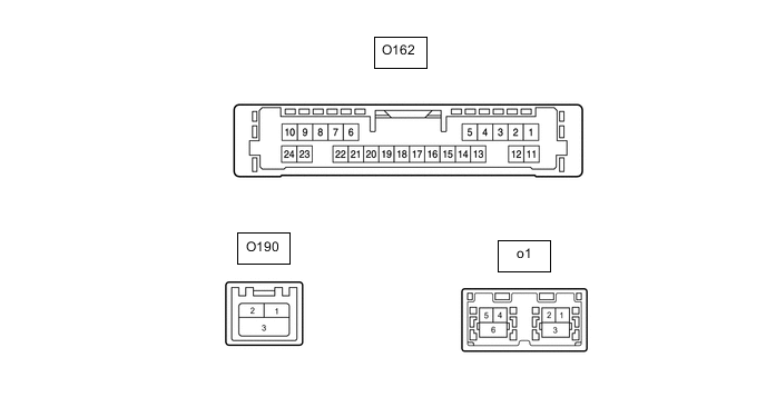
Terminal No. (Symbol) Wiring Color Terminal Description Condition Specified Condition O162-6 (VOI+) - O162-23 (GND) R - W-B Voice signal Voice guidance sounding A waveform synchronized with sound is output O162-7 (VOI-) - O162-23 (GND) L - W-B Voice signal Voice guidance sounding A waveform synchronized with sound is output O162-8 (SLD1) - Body ground Shielded - Body ground Shield ground Always Below 1 Ω O162-9 (SPD) - O162-23 (GND) L - W-B Vehicle speed signal See "Check GPS and Vehicle Sensors" in Operation Check
- O162-10 (+B) - O162-23 (GND) V - W-B Power source (+B) Always 11 to 14 V*3
10.5 to 16 V*4
O162-13 (MIC+) - O162-23 (GND) B - W-B Microphone voice signal See "Microphone Check (MEU)" in Operation Check
- O162-14 (MIC-) - Body ground W - Body ground Microphone voice signal See "Microphone Check (MEU)" in Operation Check
- O162-19 (REV2) - O162-23(GND) G - W-B Reverse signal Engine running, shift position not in R → in R 2 V or less → 11 to 14 V O162-21 (SUP) - O162-23 (GND) LG - W-B Power source (ACC) 20 seconds elapse after turning the engine switch on (ACC) 11 to 14 V O162-22 (RST)*2 SB - - - O162-23 (GND) - Body ground W-B - Body ground Ground Always Below 1 Ω O190-1 (USB+)*1 - USB communication line - - O190-2 (USB-)*1 - USB communication line - - O190-3 (USBS) - Body ground*1 Shielded - Body ground Shield ground Always Below 1 Ω o1-1 (GVIF-) - Video signal (Digital) - - o1-2 (GVIF+) - Video signal (Digital) - - o1-3 (GND) - Body ground Shielded - Body ground Shield ground Always Below 1 Ω o1-4 (USB+) - USB communication line - - o1-5 (USB-) - USB communication line - - o1-6 (USBS) - Body ground Shielded - Body ground Shield ground Always Below 1 Ω *1: w/ Telematics Transceiver for G-BOOK
*2: It is connected, but not used
*3: w/o Stop and Start System
*4: w/ Stop and Start System
-
STEREO COMPONENT AMPLIFIER ASSEMBLY
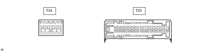
Terminal No. (Symbol) Wiring Color Terminal Description Condition Specified Condition T20-1 (+B) - T20-3 (GND)*2 SB - BR*3
R - BR*4
Power source (+B) Always 11 to 14 V*3
9.5 to 14 V*4
T20-2 (TMUT) - Body ground*1 B - Body ground Mute signal Audio system playing 3.0 to 5.0 V Emergency call mode Below 1 V T20-3 (GND) - Body ground BR - Body ground Ground Always Below 1 Ω T20-4 (WFL+) - T20-3 (GND) R - BR Sound signal (Front Left) Audio system playing A waveform synchronized with sound signals is output T20-5 (WFR+) - T20-3 (GND) L - BR Sound signal (Front Right) Audio system playing A waveform synchronized with sound signals is output T20-6 (WF1+) - T20-3 (GND) GR - BR Sound signal (Woofer) Audio system playing A waveform synchronized with sound signals is output T20-7 (CTR+) - T20-3 (GND) GR - BR Sound signal (Front Center) Audio system playing A waveform synchronized with sound signals is output T20-8 (RL+) - T20-3 (GND) BE - BR Sound signal (Rear Left) Audio system playing A waveform synchronized with sound signals is output T20-9 (RR+) - T20-3 (GND) LG - BR Sound signal (Rear Right) Audio system playing A waveform synchronized with sound signals is output T20-10 (SL+) - T20-3 (GND)*2 B - BR Sound signal (Rear Left) Audio system playing A waveform synchronized with sound signals is output T20-11 (SR+) - T20-3 (GND)*2 W - BR Sound signal (Rear Right) Audio system playing A waveform synchronized with sound signals is output T20-12 (FL+) - T20-3 (GND) W - BR Sound signal (Front Left) Audio system playing A waveform synchronized with sound signals is output T20-13 (FR+) - T20-3 (GND) BE - BR Sound signal (Front Right) Audio system playing A waveform synchronized with sound signals is output T20-16 (+B2) - T20-3 (GND) BE - BR*3
R - BR*4
Power source (+B) Always 11 to 14 V*3
9.5 to 14 V*4
T20-17 (SPD) - T20-3 (GND) L - BR Vehicle speed signal Engine switch on (IG)
Wheel being rotated
Pulse generation T20-18 (GND2) - Body ground BR - Body ground Ground Always Below 1 Ω T20-19 (WFL-) - T20-3 (GND) B - BR Sound signal (Front Left) Audio system playing A waveform synchronized with sound signals is output T20-20 (WFR-) - T20-3 (GND) B - BR Sound signal (Front Right) Audio system playing A waveform synchronized with sound signals is output T20-21 (WF1-) - T20-3 (GND) L - BR Sound signal (Woofer) Audio system playing A waveform synchronized with sound signals is output T20-22 (CTR-) - T20-3 (GND) V - BR Sound signal (Front Center) Audio system playing A waveform synchronized with sound signals is output T20-23 (RL-) - T20-3 (GND) P - BR Sound signal (Rear Left) Audio system playing A waveform synchronized with sound signals is output T20-24 (RR-) - T20-3 (GND) W - BR Sound signal (Rear Right) Audio system playing A waveform synchronized with sound signals is output T20-25 (SL-) - T20-3 (GND)*2 V - BR Sound signal (Rear Left) Audio system playing A waveform synchronized with sound signals is output T20-26 (SR-) - T20-3 (GND)*2 GR - BR Sound signal (Rear Right) Audio system playing A waveform synchronized with sound signals is output T20-27 (FL-) - T20-3 (GND) P - BR Sound signal (Front Left) Audio system playing A waveform synchronized with sound signals is output T20-28 (FR-) - T20-3 (GND) P - BR Sound signal (Front Right) Audio system playing A waveform synchronized with sound signals is output T34-2 (MI+) B MOST communication signal - - T34-3 (MI-) B MOST communication signal - - T34-4 (SLDI) Shielded Shield ground - - T34-5 (MO+) B MOST communication signal - - T34-6 (MO-) B MOST communication signal - - T34-7 (SLDO) Shielded Shield ground - - T34-8 (WUI) W MOST communication wake-up signal - -
-
*1: w/ Telematics Transceiver
*2: for 17 Speakers
*3: w/o Stop and Start System
*4: w/ Stop and Start System
-
-
MULTI-DISPLAY ASSEMBLY

Terminal No. (Symbol) Wiring Color Terminal Description Condition Specified Condition O60-2 (ILL) - O60-13 (GND1) G - W-B Illumination signal Light control switch off Below 1 V Light control switch in tail or head position 11 to 14 V O60-7 (TX+) G AVC-LAN communication signal - - O60-11 (VMTI) - O60-13 (GND1) W - W-B Visual mute signal When image on display switches 3.5 V or higher
→ Below 1 V
→ 3.5 V or higher
O60-12 (B) - O60-13 (GND1) V - W-B Power source (+B) Always 11 to 14 V*1
10.5 to 16 V*2
O60-13 (GND1) - Body ground W-B - Body ground Ground Always Below 1 Ω O60-19 (TX-) V AVC-LAN communication signal - - O60-24 (ACC) - O60-13 (GND1) BE - W-B*1
GR - W-B*2
Power source (ACC) Engine switch off Below 1 V Engine switch on (ACC) 11 to 14 V*1
10.5 to 16 V*2
O189-1 (GVIF+) - Video signal (Digital) - - O189-2 (GVIF-) - Video signal (Digital) - - O189-3 (GND) Shielded Shield ground - -
-
*1: w/o Stop and Start System
*2: w/ Stop and Start System
-
-
REMOTE TOUCH (REMOTE OPERATION CONTROLLER ASSEMBLY)

Terminal No. (Symbol) Wiring Color Terminal Description Condition Specified Condition O165-1 (+B) - O165-10 (GND) V - W-B Power source (+B) Always 11 to 14 V*1
10.5 to 16 V*2
O165-2 (ILL+) - O165-10 (GND) G - W-B*1
W - W-B*2
Illumination signal Light control switch off Below 1 V Light control switch in tail or head position 11 to 14 V*1
10.5 to 16 V*2
O165-5 (ILL-) - O165-10 (GND) BE - W-B Illumination signal Light control switch off Below 1 V Light control switch in tail or head position Pulse generation O165-6 (ACC) - O165-10 (GND) BE - W-B*1
SB - W-B*2
Power source (ACC) Engine switch on (ACC) 11 to 14 V*1
10.5 to 16 V*2
Engine switch off Below 1 V O165-8 (MO-) B Local bus communication signal - - O165-9 (MO+) GR Local bus communication signal - - O165-10 (GND) - Body ground W-B - Body ground Ground Always Below 1 Ω
-
*1: w/o Stop and Start System
*2: w/ Stop and Start System
-
-
COMBINATION METER ASSEMBLY
-
TELEMATICS TRANSCEIVER (w/ Telematics Transceiver for G-BOOK)
-
TELEMATICS TRANSCEIVER (w/ Telematics Transceiver except G-BOOK)