REAR POWER OUTLET SOCKET REMOVAL

-
REMOVE REAR NO. 2 SEAT HEADREST ASSEMBLY LH (for LH Side)
-
REMOVE REAR SEAT CUSHION HINGE COVER LH
-
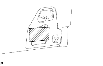
Apply protective tape to the rear seatback lock striker as shown in the illustration to prevent the seat from locking.
-
Operate the power seat switch and move the seat to the storage position.
Tech Tips
Make sure that the lock and striker are not engaged.
-
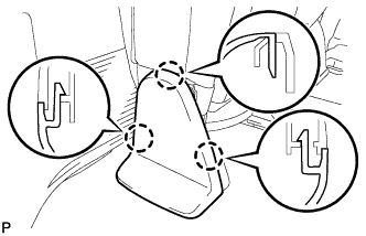
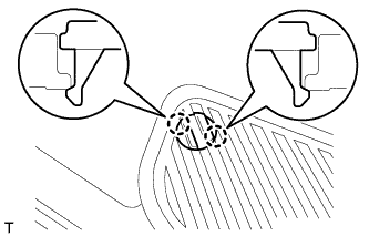
Using a screwdriver, detach the 3 claws and remove the cover.
Tech Tips
Tape the screwdriver tip before use.
-
-
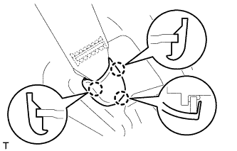
REMOVE REAR NO. 2 SEAT HINGE COVER LH
-
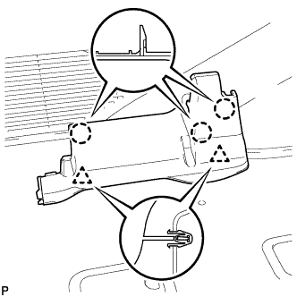
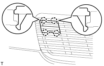
Detach the 3 claws and 2 clips, and then remove the cover.
-
-
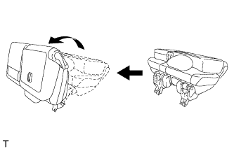
REMOVE REAR NO. 2 SEAT ASSEMBLY
-
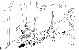
Disconnect the connector.
-
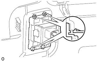
Remove the 4 bolts and seat assembly.
Note
Be careful not to damage the vehicle body.
-
-
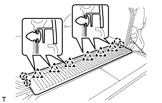
REMOVE REAR STEP COVER
Tech Tips
Use the same procedure to remove the step cover on the other side.
-
w/o Illumination Type Front Door Scuff Plate:
Detach the 2 claws and remove the step cover.
-
w/ Illumination Type Front Door Scuff Plate:
Detach the 4 claws and remove the step cover.
-
-
REMOVE REAR DOOR SCUFF PLATE LH
-
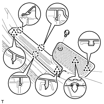
w/o Illumination Type Front Door Scuff Plate:
Remove the rear door scuff plate.
-
Remove the screw.
-
Detach the 3 claws and 4 clips, and remove the scuff plate.
-
-
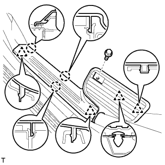
w/ Illumination Type Front Door Scuff Plate:
Remove the rear door scuff plate.
-
Remove the screw.
-
Detach the 3 claws and 4 clips, and remove the scuff plate.
-
-
-
REMOVE REAR FLOOR MAT REAR SUPPORT PLATE
-
Detach the 6 clips and 4 claws, and remove the support plate.
-
-
REMOVE FRONT QUARTER TRIM PANEL ASSEMBLY LH
Tech Tips
When removing the front quarter trim panel, operate the reclining adjuster release handle and move the No. 1 rear seat to the position shown in the illustration.
-
Detach the 3 claws and remove the cover.
-
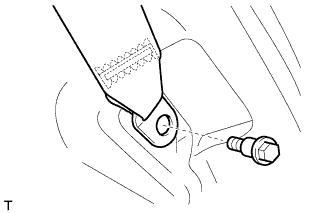
Remove the bolt and rear No. 1 seat belt anchor.
-
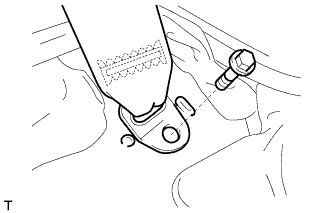
Remove the bolt and rear No. 2 seat belt anchor.
-
Remove the clip.
-
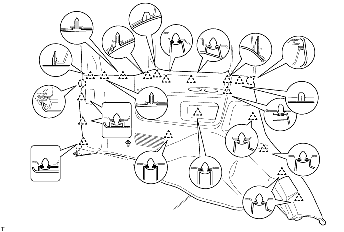
Detach the 19 clips and 2 claws.
-
Disconnect the thermistor connector and then remove the quarter trim panel.
-
-
REMOVE POWER OUTLET SOCKET ASSEMBLY (for Type A)
-
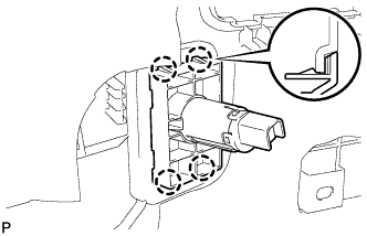
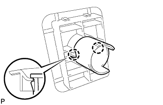
Disengage the 4 claws and remove the power outlet socket bezel.
-
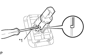
Text in Illustration *1 Protective Tape Using a screwdriver with its tip wrapped in protective tape, disengage the claw and remove the power outlet socket assembly.
-
-
REMOVE POWER OUTLET SOCKET COVER NO.2 (for Type A)
-
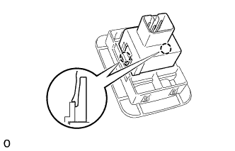
Disengage the 2 claws and remove the power outlet socket cover.
-
-
REMOVE POWER OUTLET SOCKET BEZEL (for Type B)
-
Detach the 4 claws and remove the power outlet socket bezel.
-
-
REMOVE POWER OUTLET SOCKET (for Type B)
-
Detach the 2 claws and remove the power outlet socket.
-