FRONT EVAPORATOR TEMPERATURE SENSOR (for RHD) REASSEMBLY

-
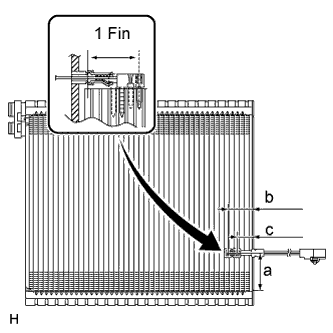
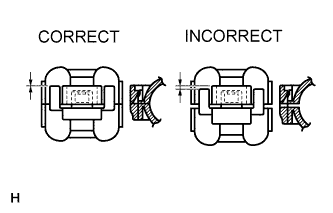
INSTALL FRONT EVAPORATOR TEMPERATURE SENSOR
Note
If reusing the evaporator, do not insert the sensor at a location where the sensor was previously inserted.
-
Insert the sensor at a location that is 1 fin to the right or left of its previous location.
Standard Dimension Area Specified Condition a 50 mm (1.97 in.) b 34.3 mm (1.35 in.) c 20.9 mm (0.822 in.)
-
-
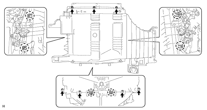
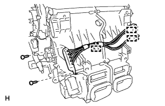
INSTALL NO. 1 COOLER EVAPORATOR SUB-ASSEMBLY
-
Install the evaporator.
-
Attach the 6 claws to install the unit case.
-
Install the 7 screws.
-
-
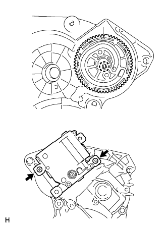
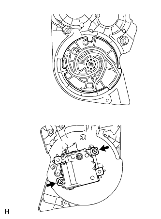
INSTALL SERVO MOTOR
-
Install the rear air mix damper control servo motor RH.
-
Attach the claw to install the lever and servo motor.
-
Install the 2 screws.
-
-
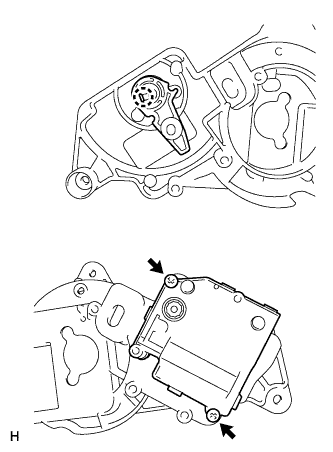
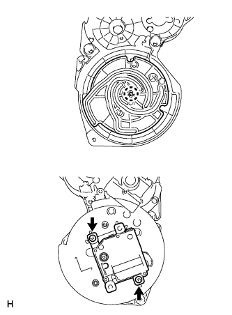
Install the rear mode control servo motor.
-
Attach the claw to install the plate and servo motor.
-
Install the 2 screws.
-
-
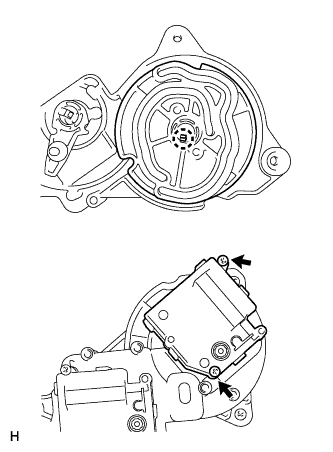
Set the damper servo so that the cutout part engages with the tooth of the gear, and attach the claw to install the servo motor unit.
-
Install the 3 screws.
-
-
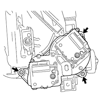
INSTALL SERVO MOTOR
-
Install the front air mix damper control servo motor LH.
-
Attach the claw to install the plate and servo motor.
-
Install the 2 screws.
-
-
Install the front mode control servo motor LH.
-
Attach the claw to install the plate and servo motor.
-
Install the 2 screws.
-
-
Install the control air bypass damper control servo motor LH.
-
Attach the claw to install the plate and servo motor.
-
Install the 2 screws.
-
-
Set the damper servo so that the cutout part engages with the tooth of the gear, and attach the claw to install the servo motor unit.
-
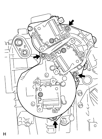
Install the 4 screws.
-
-
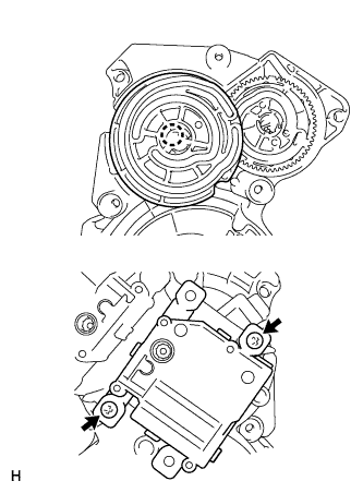
INSTALL SERVO MOTOR
-
Install the front air mix damper control servo motor RH.
-
Attach the claw to install the plate and servo motor.
-
Install the 2 screws.
-
-
Install the control air bypass damper control servo motor RH.
-
Attach the claw to install the plate and servo motor.
-
Install the 2 screws.
-
-
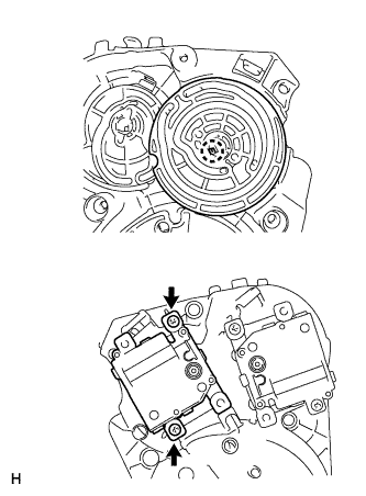
Install the front mode control servo motor RH.
-
Attach the claw to install the plate and servo motor.
-
Install the 2 screws.
-
-
Set the damper servo so that the cutout part engages with the tooth of the gear, and attach the claw to install the servo motor unit.
-
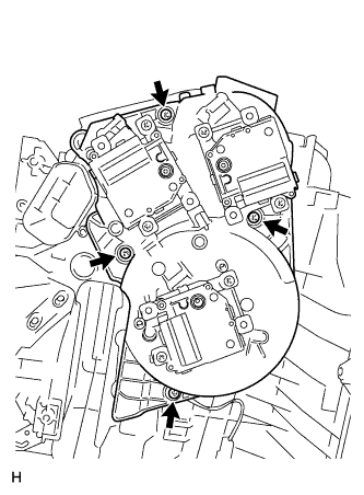
Install the 4 screws.
-
-
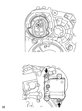
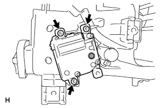
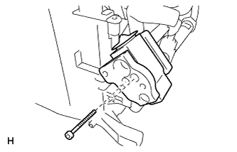
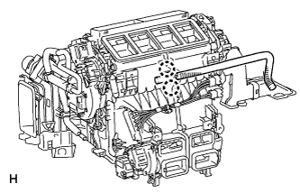
INSTALL REAR AIR MIX DAMPER CONTROL SERVO MOTOR RH
-
Install the servo motor with the 3 screws.
-
-
INSTALL COOLER EXPANSION VALVE (w/o Cool Box)
-
Sufficiently apply compressor oil to 4 new O-rings and the fitting surface of the hose joint.
Compressor oil ND-OIL 8 or equivalent -
Install 2 O-rings to the cooler evaporator.
-
Install 2 O-rings to the air conditioner tube and accessory assembly.
-
Install the cooler expansion valve and air conditioner tube and accessory assembly to the evaporator.
-
Using a 4 mm hexagon wrench, install the 2 bolts.
- Torque:
- 3.5 N*m { 36 kgf*cm, 31 in.*lbf }
-
Install new packing.
-
-
INSTALL AIR CONDITIONER TUBE AND ACCESSORY ASSEMBLY (w/ Cool Box)
-
Sufficiently apply compressor oil to 2 new O-rings and the fitting surface of the hose joint.
Compressor oil ND-OIL 8 or equivalent -
Install the 2 O-rings to the air conditioner tube and accessory assembly.
-
Install the air conditioner tube and accessory assembly to the evaporator.
-
Using a 4 mm hexagon wrench, install the 2 hexagon bolts.
- Torque:
- 3.5 N*m { 36 kgf*cm, 31 in.*lbf }
-
Install the bracket with the screw.
-
-
INSTALL COOLER EXPANSION VALVE (w/ Cool Box)
-
Sufficiently apply compressor oil to 2 new O-rings and the fitting surface of the hose joint.
Compressor oil ND-OIL 8 or equivalent -
Install the 2 O-rings to the No. 2 connector tube.
-
Install the No. 2 connector tube, expansion valve and No. 3 connector tube.
-
Using a 4 mm hexagon wrench, install the 2 hexagon bolts.
- Torque:
- 3.5 N*m { 36 kgf*cm, 31 in.*lbf }
-
Sufficiently apply compressor oil to 2 new O-rings and the fitting surface of the hose joint.
Compressor oil ND-OIL 8 or equivalent -
Install the 2 O-rings to the No. 1 connector tube.
-
Install the No. 1 connector tube.
-
Using a 4 mm hexagon wrench, install the 2 hexagon bolts.
- Torque:
- 3.5 N*m { 36 kgf*cm, 31 in.*lbf }
-
Using a 4 mm hexagon wrench, install the bracket with the hexagon bolt and screw.
-
Install new butyl tape.
-
Install new packing.
-
-
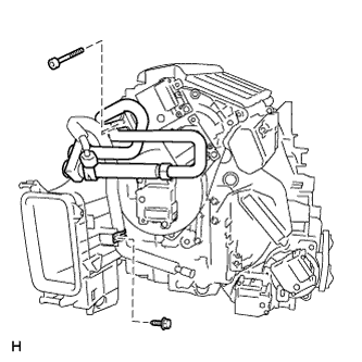
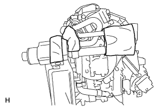
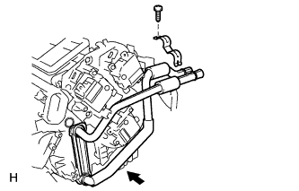
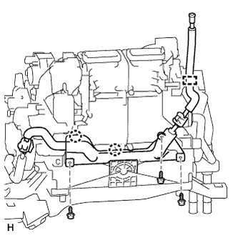
INSTALL AIR CONDITIONING RADIATOR ASSEMBLY
-
Install the radiator.
-
Install the bracket with the screw.
-
-
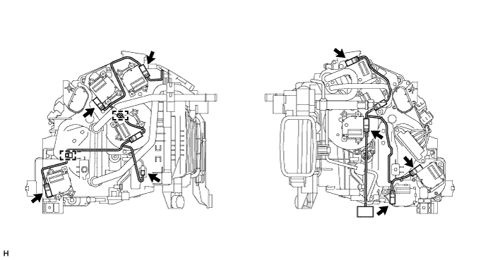
INSTALL AIR CONDITIONER HARNESS
-
Attach the clamps to install the harness.
-
Connect the connectors.
-
-
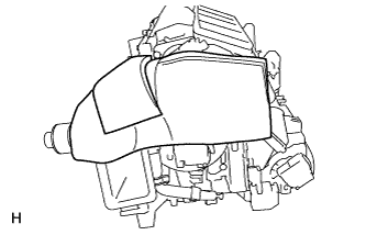
INSTALL QUICK HEATER ASSEMBLY (w/ PTC Heater)
-
Install the quick heater with the 2 screws.
-
Attach the 3 clamps.
-
-
INSTALL COOL BOX LIQUID TUBE (w/ Cool Box)
-
Lubricate 2 new O-rings with compressor oil and install them to the liquid tube.
Compressor oil ND-OIL 8 or equivalent -
Connect the liquid tube with the piping clamp.
Note
After connection, check the claw engagement of the piping clamp.
-
Attach the clamp.
-
Attach the 2 claws to install the protective cover.
-
Install the 3 screws.
-
-
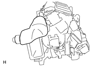
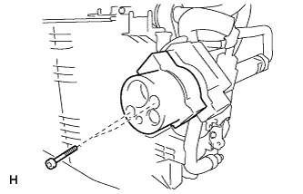
INSTALL ASPIRATOR
-
Attach the 2 claws to install the aspirator.
-
-
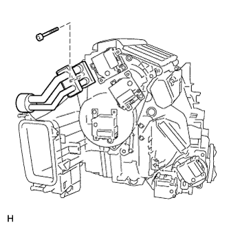
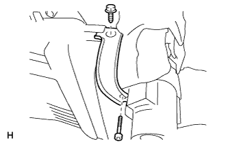
INSTALL NO. 4 AIR DUCT SUB-ASSEMBLY
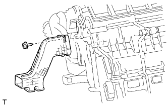
-
Install the duct with the screw.
-
-
INSTALL NO. 5 AIR DUCT SUB-ASSEMBLY
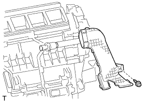
-
Install the duct with the screw.
-
-
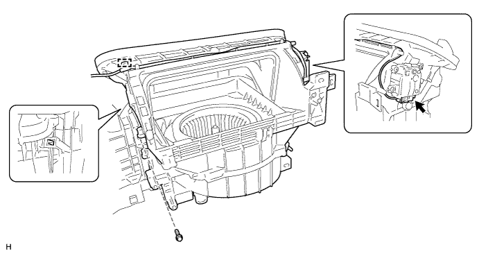
INSTALL BLOWER ASSEMBLY
-
Attach the claw to install the blower unit.
-
Connect the connector and clamp.
-
Install the screw.
-