FRONT EVAPORATOR TEMPERATURE SENSOR (for LHD) DISASSEMBLY

-
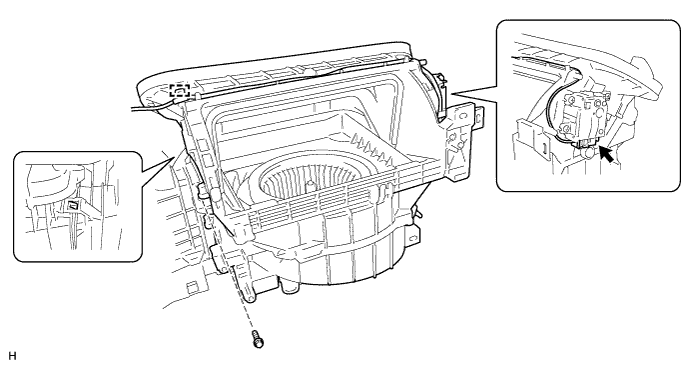
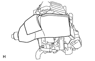
REMOVE BLOWER ASSEMBLY
-
Remove the screw.
-
Disconnect the connector and clamp.
-
Detach the claw and remove the blower unit.
-
-
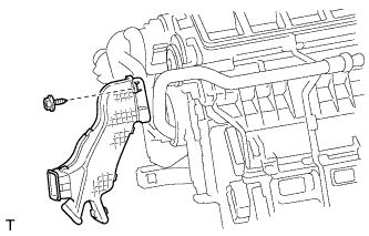
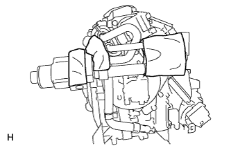
REMOVE NO. 4 AIR DUCT SUB-ASSEMBLY
-
Remove the screw and duct.
-
-
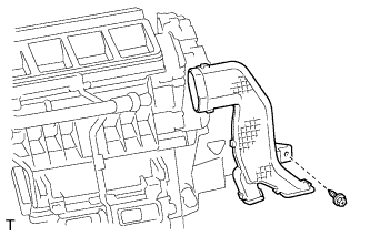
REMOVE NO. 5 AIR DUCT SUB-ASSEMBLY
-
Remove the screw and duct.
-
-
REMOVE ASPIRATOR
-
Detach the 2 claws and remove the aspirator.
-
-
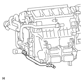
REMOVE COOL BOX LIQUID TUBE (w/ Cool Box)
-
Detach the clamp.
-
Using SST, remove the piping clamp.
- SST
- 09870-00025
-
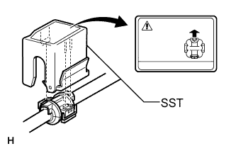
Attach SST to the piping clamp.
Tech Tips
Confirm the direction of the piping clamp claw and SST by referring to the illustration on the caution label.
-
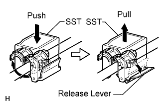
Push down SST and release the clamp lock.
Note
Be careful not to deform the tubes when pushing SST.
-
Pull SST slightly and push the release lever, then remove the piping clamp with SST.
-
Remove the piping clamp from SST.
-
Disconnect the tube.
Note
Cap the open fittings immediately to keep moisture or dirt out of the system.
-
Remove the 2 O-rings from the tube.
-
-
REMOVE QUICK HEATER ASSEMBLY (w/ PTC Heater)
-
Detach the 3 clamps.
-
Remove the 2 screws and quick heater.
-
-
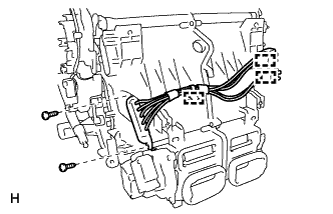
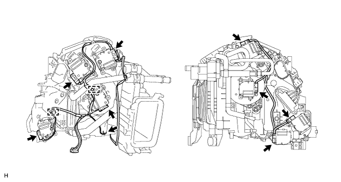
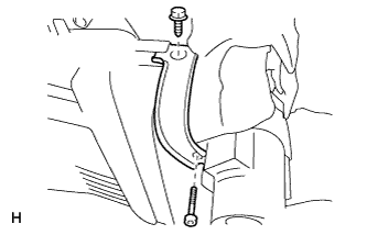
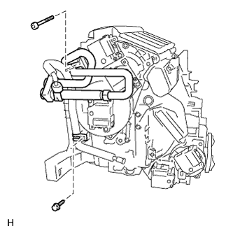
REMOVE AIR CONDITIONER HARNESS
-
Disconnect the connectors.
-
Detach the clamps and remove the harness.
-
-
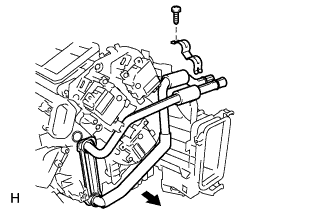
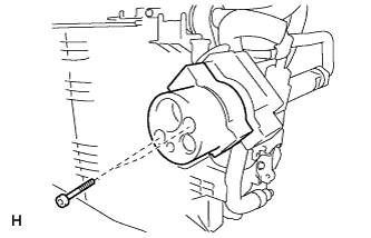
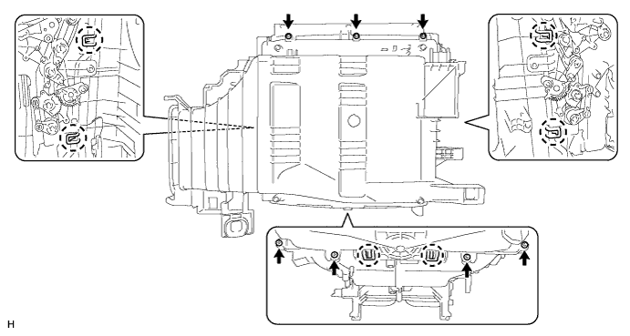
REMOVE AIR CONDITIONING RADIATOR ASSEMBLY
-
Remove the screw and radiator bracket.
-
Remove the radiator.
-
-
REMOVE COOLER EXPANSION VALVE (w/ Cool Box)
-
Remove the packing.
-
Remove the butyl tape.
-
Using a 4 mm hexagon wrench, remove the hexagon bolt, screw and bracket.
-
Using a 4 mm hexagon wrench, remove the 2 hexagon bolts and No. 1 connector tube.
-
Remove the 2 O-rings from the No. 1 connector tube.
-
Using a 4 mm hexagon wrench, remove the 2 hexagon bolts, No. 2 connector tube, expansion valve and No. 3 connector tube.
-
Remove the 2 O-rings from the No. 2 connector tube.
-
-
REMOVE AIR CONDITIONER TUBE AND ACCESSORY ASSEMBLY (w/ Cool Box)
-
Remove the screw and bracket.
-
Using a 4 mm hexagon wrench, remove the 2 hexagon bolts and air conditioner tube and accessory assembly.
-
Remove the 2 O-rings from the air conditioner tube and accessory assembly.
-
-
REMOVE COOLER EXPANSION VALVE (w/o Cool Box)
-
Remove the packing.
-
Remove the butyl tape.
-
Using a 4 mm hexagon wrench, remove the hexagon bolt, screw and bracket.
-
Using a 4 mm hexagon wrench, remove the 2 hexagon bolts and No. 1 connector tube.
-
Remove the 2 O-rings from the No. 1 connector tube.
-
Using a 4 mm hexagon wrench, remove the 2 hexagon bolts, No. 2 connector tube, expansion valve and No. 3 connector tube.
-
Remove the 2 O-rings from the No. 2 connector tube.
-
-
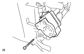
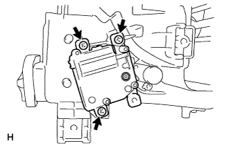
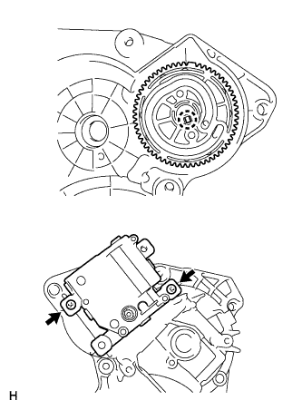
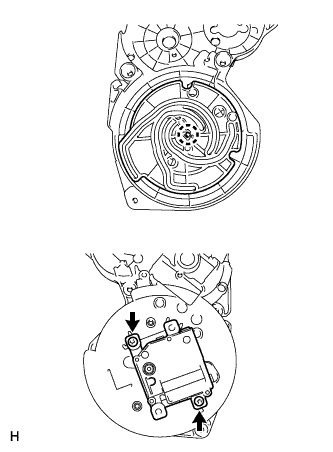
REMOVE REAR AIR MIX DAMPER CONTROL SERVO MOTOR RH
-
Remove the 3 screws and servo motor.
-
-
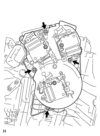
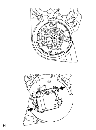
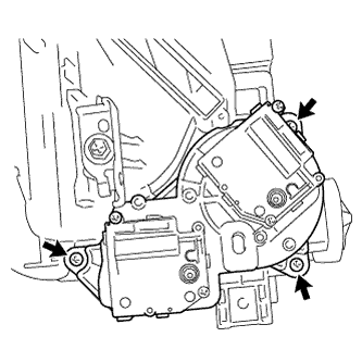
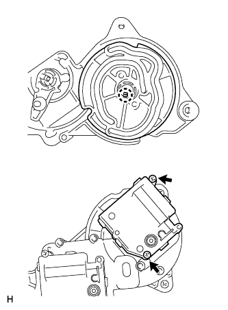
REMOVE SERVO MOTOR
-
Remove the 4 screws and servo motor unit.
-
Remove the front mode control servo motor RH.
-
Remove the 2 screws.
-
Detach the claw and remove the plate and servo motor.
Note
Be careful not to damage the claw of the plate.
-
-
Remove the control bypass damper control servo motor.
-
Remove the 2 screws.
-
Detach the claw and remove the plate and servo motor.
Note
Be careful not to damage the claw of the plate.
-
-
Remove the front air mix damper control servo motor RH.
-
Remove the 2 screws.
-
Detach the claw and remove the plate and servo motor.
Note
Be careful not to damage the claw of the plate.
-
-
-
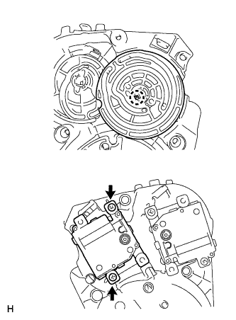
REMOVE SERVO MOTOR
-
Remove the 4 screws and servo motor unit.
-
Detach the 3 claws and remove the plate.
Note
Be careful not to damage the claw of the plate.
-
Remove the front mode control servo motor LH.
-
Remove the 2 screws.
-
Detach the claw and remove the plate and servo motor.
Note
Be careful not to damage the claw of the plate.
-
-
Remove the front air mix damper control servo motor LH.
-
Remove the 2 screws.
-
Detach the claw and remove the plate and servo motor.
Note
Be careful not to damage the claw of the plate.
-
-
-
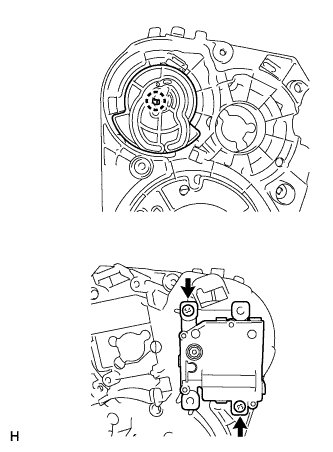
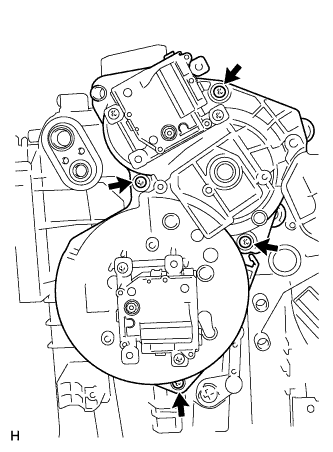
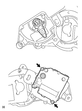
REMOVE SERVO MOTOR
-
Remove the 3 screws and servo motor unit.
-
Remove the rear mode control servo motor.
-
Remove the 2 screws.
-
Detach the claw and remove the plate and servo motor.
Note
Be careful not to damage the claw of the plate.
-
-
Remove the rear air mix damper control servo motor RH.
-
Remove the 2 screws.
-
Detach the claw and remove the lever and servo motor.
Note
Be careful not to damage the claw of the lever.
-
-
-
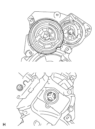
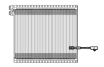
REMOVE NO. 1 COOLER EVAPORATOR SUB-ASSEMBLY
-
Remove the 7 screws.
-
Detach the 6 claws and remove the unit case.
-
Remove the evaporator.
-
-
REMOVE FRONT EVAPORATOR TEMPERATURE SENSOR
-
Remove the sensor from the evaporator.
-