ROOM TEMPERATURE SENSOR (for Front Side) INSTALLATION

Tech Tips
-
Use the same procedures for LHD and RHD vehicles.
-
The procedures listed below are for LHD vehicles.
-
INSTALL ROOM TEMPERATURE SENSOR
-
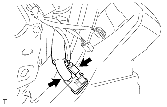
Install the sensor and connect the hose.
-
Connect the connector.
-
-
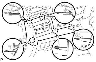
INSTALL LOWER NO. 1 INSTRUMENT PANEL FINISH PANEL
-
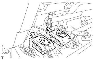
Connect the connectors.
-
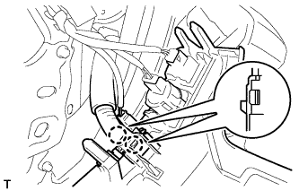
Attach the 2 claws to install the sensor.
-
Attach the 2 claws to connect the 2 control cables.
-
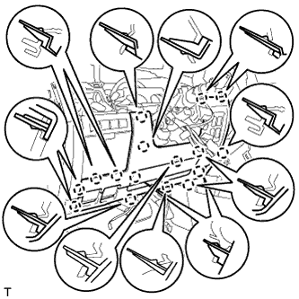
Attach the 16 claws to install the finish panel.
-
Install the 2 bolts.
-
Attach the 2 claws to close the hole cover.
-
-
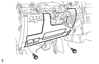
INSTALL NO. 1 INSTRUMENT PANEL UNDER COVER SUB-ASSEMBLY
-
Connect the connectors.
-
Attach the 3 claws to install the under cover.
-
Install the 2 screws.
-
-
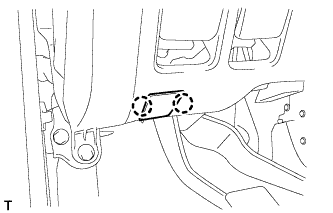
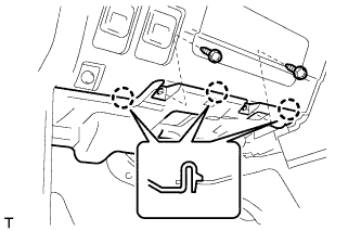
INSTALL NO. 1 SWITCH HOLE BASE
-
Connect the connectors.
-
Attach the 5 claws to install the switch hole base.
-
-
INSTALL INSTRUMENT SIDE PANEL LH
-
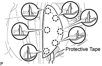
Place protective tape as shown in the illustration.
-
Using a moulding remover, detach the 6 claws and remove the side panel.
-
-
INSTALL INNER NO. 1 INSTRUMENT PANEL BRACKET COVER LH
-
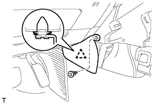
Attach the clip to install the cover.
-
Install the clip.
-
-
INSTALL LOWER INSTRUMENT PANEL PAD SUB-ASSEMBLY LH
-
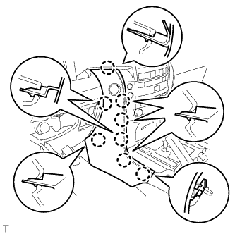
Connect the connector.
-
Attach the 8 claws to install the panel pad.
-
-
CONNECT CABLE TO NEGATIVE BATTERY TERMINAL
Note
When disconnecting the cable, some systems need to be initialized after the cable is reconnected Click here.
-
INSTALL ENGINE ROOM SIDE COVER LH
-
Install the engine room side cover LH with the 7 clips.
-
-
CHECK SRS WARNING LIGHT