CONDENSER INSTALLATION

-
INSTALL COOLER DRYER
-
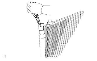
Using pliers, install the cooler dryer.
-
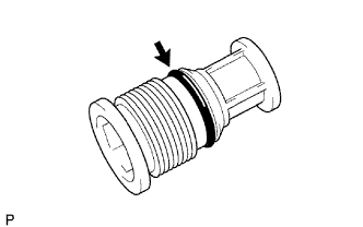
Apply a sufficient amount of compressor oil to the contact surfaces of a new O-ring and the cap.
Compressor oil ND-OIL 8 or equivalent -
Install the O-ring to the cap.
-
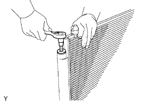
Using a 14 mm socket hexagon wrench, install the cap to the modulator.
- Torque:
- 2.9 N*m { 30 kgf*cm, 26 in.*lbf }
-
-
INSTALL COOLER CONDENSER ASSEMBLY
-
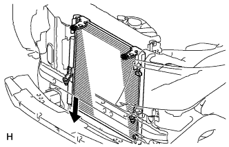
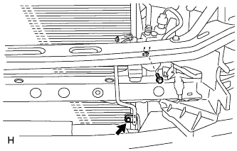
Install the cooler condenser as shown in the illustration.
-
-
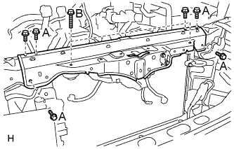
INSTALL RADIATOR SUPPORT SUB-ASSEMBLY
-
Install the radiator support with the 8 bolts.
- Torque:
- 21.7 N*m { 221 kgf*cm, 16 ft.*lbf, for bolt A }
- 9.8 N*m { 100 kgf*cm, 87 in.*lbf, for bolt B }
-
-
INSTALL HOOD LOCK ASSEMBLY
-
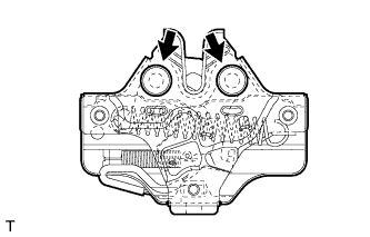
Apply MP grease to the sliding areas of the lock.
-
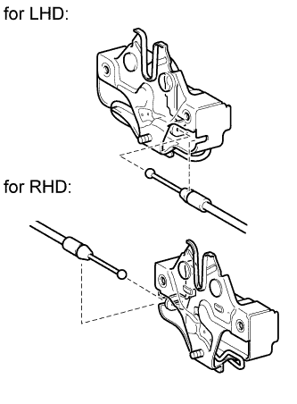
Connect the hood lock control cable.
-
Install the hood lock.
-
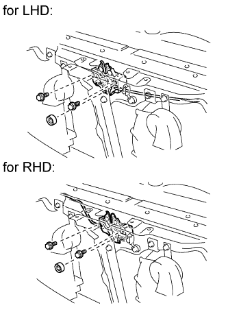
Install the 2 bolts and nut.
- Torque:
- 5.5 N*m { 56 kgf*cm, 49 in.*lbf }
-
Connect the connector.
-
-
INSTALL HOOD LOCK CONTROL CABLE COVER
-
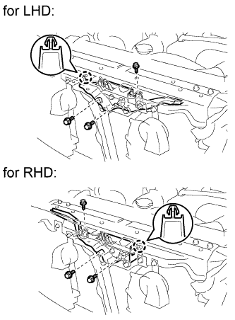
Attach the claw to install the cable cover.
-
Install the 3 screws.
-
-
INSTALL HOOD LOCK SUPPORT BRACE SUB-ASSEMBLY
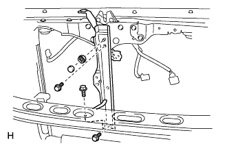
-
Install the brace with the 3 bolts and nut.
- Torque:
- 21.7 N*m { 221 kgf*cm, 16 ft.*lbf, for bolt }
- 5.5 N*m { 56 kgf*cm, 49 in.*lbf, for nut }
-
Install the hood lock nut cap.
-
-
INSTALL OIL COOLER ASSEMBLY
-
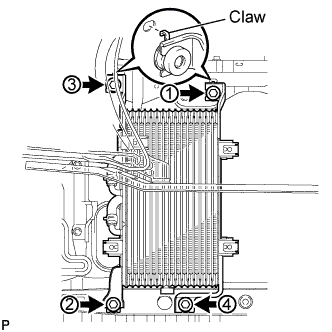
Temporarily install the oil cooler to the radiator support.
Note
Securely attach the 2 claws of the oil cooler into the hole of the radiator support.
-
Install the 4 bolts in the sequence shown in the illustration.
- Torque:
- 12 N*m { 122 kgf*cm, 9 ft.*lbf }
-
-
INSTALL TRANSMISSION OIL COOLER AIR DUCT
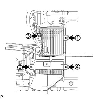
-
Install the oil cooler air duct with the 4 bolts in the sequence shown in the illustration.
- Torque:
- 4.9 N*m { 50 kgf*cm, 43 in.*lbf }
-
-
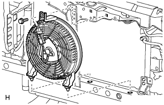
INSTALL SHROUD BLOWER ASSEMBLY
-
Install the shroud blower with the bolt.
- Torque:
- 9.8 N*m { 100 kgf*cm, 87 in.*lbf }
-
Connect the connector.
-
-
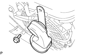
INSTALL LOW PITCHED HORN ASSEMBLY
-
Connect the connector.
-
Install the low pitched horn assembly with the bolt.
- Torque:
- 19 N*m { 194 kgf*cm, 14 ft.*lbf }
-
-
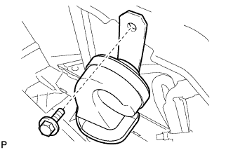
INSTALL HIGH PITCHED HORN ASSEMBLY
-
Connect the connector.
-
Install the high pitched horn assembly with the bolt.
- Torque:
- 19 N*m { 194 kgf*cm, 14 ft.*lbf }
-
-
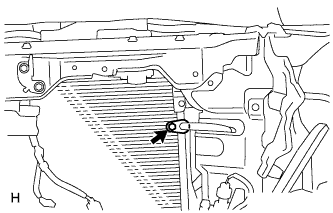
CONNECT NO. 1 COOLER REFRIGERANT DISCHARGE HOSE
-
Remove the attached vinyl tape from the hose and the connecting part of the cooler condenser.
-
Sufficiently apply compressor oil to a new O-ring and the fitting surface of the discharge hose joint.
Compressor oil ND-OIL 8 or equivalent -
Install the O-ring to the discharge hose.
-
Connect the discharge hose to the cooler condenser with the bolt.
- Torque:
- 5.4 N*m { 55 kgf*cm, 48 in.*lbf }
Note
-
When tightening the bolt, do not allow any tools to contact the pipe.
-
When tightening the bolt, hold a part of the pipe near the connector.
-
-
CONNECT COOLER REFRIGERANT LIQUID PIPE A
-
Remove the attached vinyl tape from the pipe and the connecting part of the cooler condenser.
-
Sufficiently apply compressor oil to a new O-ring and the fitting surface of the liquid pipe A joint.
Compressor oil ND-OIL 8 or equivalent -
Install the O-ring to the liquid pipe A.
-
Connect the liquid pipe A to the cooler condenser with the 2 bolts.
- Torque:
- 5.4 N*m { 55 kgf*cm, 48 in.*lbf }
Note
-
When tightening the bolts, do not allow any tools to contact the pipe.
-
When tightening the bolts, hold a part of the pipe near the connector.
-
-
CONNECT CABLE TO NEGATIVE BATTERY TERMINAL
Note
When disconnecting the cable, some systems need to be initialized after the cable is reconnected Click here.
-
CHARGE REFRIGERANT
- SST
- 09985-20010 ( 09985-02130, 09985-02150, 09985-02090, 09985-02110, 09985-02010, 09985-02050, 09985-02060, 09985-02070 )
-
Perform vacuum purging using a vacuum pump.
-
Charge refrigerant HFC-134a (R134a).
Standard: Condenser Core Thickness Cool Box Refrigerant Charging Amount 22 mm (0.866 in.) w/ Cool Box 1010 +/-30 g (35.6 +/-1.1 oz.) w/o Cool Box 970 +/-30 g (34.2 +/-1.1 oz.) 16 mm (0.630 in.) w/ Cool Box 970 +/-30 g (34.2 +/-1.1 oz.) w/o Cool Box 920 +/-30 g (32.5 +/-1.1 oz.) 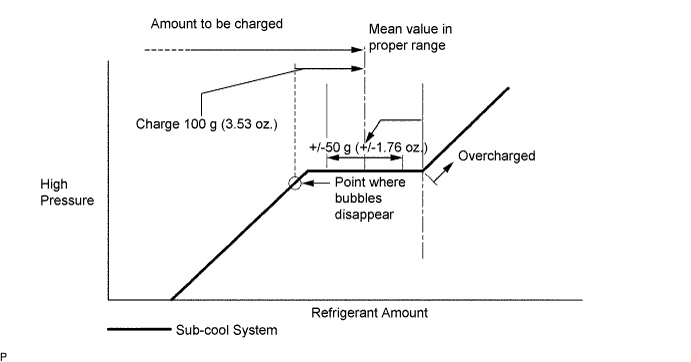
Note
-
Do not operate the cooler compressor before charging refrigerant as the cooler compressor will not work properly without any refrigerant, and will overheat.
-
Approximately 100 g (3.53 oz.) of refrigerant may need to be charged after bubbles disappear. The refrigerant amount should be checked by measuring its quantity, and not with the sight glass.
-
-
INSTALL MILLIMETER WAVE RADAR SENSOR ASSEMBLY (w/ Dynamic Radar Cruise Control System)
-
INSTALL FRONT BUMPER COVER
-
WARM UP ENGINE
-
Warm up the engine at less than 1850 rpm for 2 minutes or more after charging the refrigerant.
Note
Be sure to warm up the compressor when turning the A/C switch on after removing and installing the cooler refrigerant lines (including the compressor), to prevent damage to the compressor.
-
-
CHECK FOR REFRIGERANT GAS LEAK
-
After recharging the refrigerant gas, check for refrigerant gas leakage using a halogen leak detector.
-
Perform the operation under these conditions:
-
Stop the engine.
-
Secure good ventilation (the halogen leak detector may react to volatile gases other than refrigerant, such as evaporated gasoline or exhaust gas).
-
Repeat the test 2 or 3 times.
-
Make sure that some refrigerant remains in the refrigeration system. When compressor is off: approximately 392 to 588 kPa (4.0 to 6.0 kgf/cm2, 57 to 85 psi).
-
-
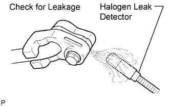
Using a halogen leak detector, check the refrigerant line for leakage.
-
If a gas leak is not detected on the drain hose, remove the blower motor control (blower resistor) from the cooling unit. Insert the halogen leak detector sensor into the unit and perform the test.
-
Disconnect the connector and wait for approximately 20 minutes. Bring the halogen leak detector close to the pressure switch and perform the test.
-
-
CHECK SRS WARNING LIGHT
-
ADJUST MILLIMETER WAVE RADAR SENSOR ASSEMBLY (w/ Dynamic Radar Cruise Control System)