FRONT AIR CONDITIONING UNIT (for LHD) INSTALLATION

-
INSTALL AIR CONDITIONING UNIT ASSEMBLY
-
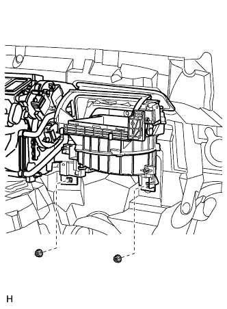
Install the air conditioning unit with the 2 nuts.
- Torque:
- 9.8 N*m { 100 kgf*cm, 87 in.*lbf }
-
-
INSTALL AIR CONDITIONING HOSE AND ACCESSORY (w/ Cool Box)
-
Lubricate 2 new O-rings with compressor oil and install them to the air conditioning hose and accessory.
Compressor oil ND-OIL 8 or equivalent -
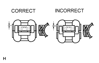
Install the air conditioning hose and accessory with the piping clamp.
Note
After connection, check the claw engagement of the piping clamp.
-
Install the bolt.
- Torque:
- 9.8 N*m { 100 kgf*cm, 87 in.*lbf }
-
-
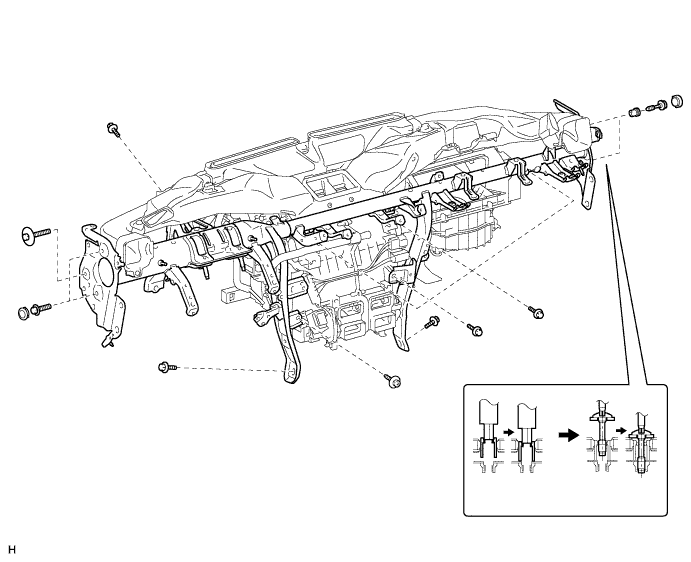
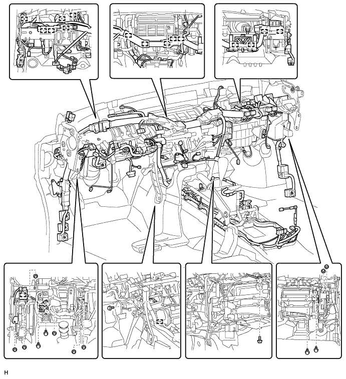
INSTALL INSTRUMENT PANEL REINFORCEMENT ASSEMBLY
-
Install the instrument panel reinforcement.
-
Install the instrument panel reinforcement with the 7 bolts and screw.
- Torque:
- for bolt
- 9.8 N*m { 100 kgf*cm, 87 in.*lbf }
- for screw
- 6.0 N*m { 61 kgf*cm, 53 in.*lbf }
-
for Passenger Side:
Using a 12 mm hexagon wrench, install the 2 collars.
- Torque:
- 18 N*m { 184 kgf*cm, 13 ft.*lbf }
-
for Passenger Side:
Using a T40 "TORX" socket, install the 2 "TORX" bolts.
- Torque:
- 18 N*m { 184 kgf*cm, 13 ft.*lbf }
-
for Passenger Side:
Install the 2 caps.
-
for Driver Side:
Install the 3 bolts.
- Torque:
- 18 N*m { 184 kgf*cm, 13 ft.*lbf }
-
for Driver Side:
Install the 3 caps.
-
-
Attach the clamps to the wire harness and connect the connectors.
-
-
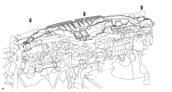
INSTALL HEATER TO REGISTER DUCT ASSEMBLY
-
Attach the 2 claws to install the duct.
-
Install the 3 clips.
-
-
INSTALL STEERING COLUMN ASSEMBLY
-
INSTALL NO. 3 AIR DUCT SUB-ASSEMBLY
-
Attach the 2 claws to install the duct.
-
Install the clip.
-
-
INSTALL INSTRUMENT PANEL SUB-ASSEMBLY
-
INSTALL FRONT WIPER MOTOR AND BRACKET
-
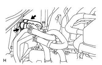
CONNECT HEATER WATER INLET HOSE AND HEATER WATER OUTLET HOSE
-
Connect the 2 heater water hoses.
-
Using pliers, grip the claws of the clips and slide the 2 clips.
-
-
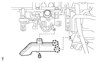
CONNECT AIR CONDITIONING TUBE ASSEMBLY
-
Remove the attached vinyl tape from the tubes.
-
Sufficiently apply compressor oil to 2 new O-rings and the fitting surface of the air conditioning tube assembly.
Compressor oil ND-OIL 8 or equivalent -
Install the 2 O-rings to the air conditioning tube assembly.
-
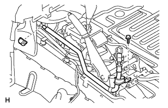
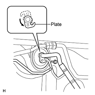
Connect the air conditioning tube assembly.
-
Attach the plate as shown in the illustration and install the bolt.
- Torque:
- 5.4 N*m { 55 kgf*cm, 47 in.*lbf }
-
-
CONNECT CABLE TO NEGATIVE BATTERY TERMINAL
Note
When disconnecting the cable, some systems need to be initialized after the cable is reconnected Click here.
-
CHECK SRS WARNING LIGHT
-
ADD ENGINE COOLANT
-
Add engine coolant.
Standard Capacity Item Specified Condition with transmission oil cooler 16.7 liters (17.6 US qts, 14.7 Imp. qts) without transmission oil cooler 16.2 liters (17.1 US qts, 14.3 Imp. qts) Note
Do not substitute plain water for engine coolant.
Tech Tips
TOYOTA vehicles are filled with TOYOTA SLLC at the factory. In order to avoid damage to the engine cooling system and other technical problems, only use TOYOTA SLLC or similar high quality ethylene glycol based non-silicate, non-amine, non-nitrite, non-borate coolant with long-life hybrid organic acid technology (coolant with long-life hybrid organic acid technology consists of a combination of low phosphates and organic acids).
-
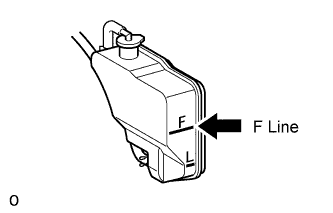
Slowly pour coolant into the radiator reservoir until it reaches the F line.
-
Install the reservoir cap.
-
Press the No. 1 and No. 2 radiator hoses several times by hand, and then check the coolant level. If the coolant level is low, add coolant.
-
Install the radiator cap.
-
Start the engine and warm it up until the thermostat opens.
Note
Switch off the A/C.
-
Maintain the engine speed at 2000 to 2500 rpm.
Note
-
Make sure that the radiator reservoir still has some coolant in it.
-
Pay attention to the needle of the water temperature meter. Make sure that the needle does not show an abnormally high temperature.
-
If there is not enough coolant, the engine may burn out or overheat.
-
Immediately after starting the engine, if the radiator reservoir does not have any coolant, perform the following: 1) stop the engine, 2) wait until the coolant has cooled down, and 3) add coolant until the coolant is filled to the F line.
-
Run the engine at 2000 rpm until the coolant level has stabilized.
-
-
Press the No. 1 and No. 2 radiator hoses several times by hand to bleed air.
CAUTION:
-
Wear protective gloves.
-
Be careful as the radiator hoses are hot.
-
Keep your hands away from the fan.
-
-
Stop the engine, and wait until the engine coolant cools down to ambient temperature.
CAUTION:
Do not remove the radiator cap while the engine and radiator are still hot. Pressurized, hot engine coolant and steam may be released and cause serious burns.
-
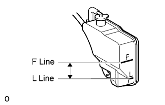
Check that the coolant level is between the F and L lines.
If the coolant level is below the L line, repeat all of the procedures above.
If the coolant level is above the F line, drain coolant so that the coolant level is between the F and L lines.
-
-
CHARGE REFRIGERANT
- SST
- 09985-20010 ( 09985-02130, 09985-02150, 09985-02090, 09985-02110, 09985-02010, 09985-02050, 09985-02060, 09985-02070 )
-
Perform vacuum purging using a vacuum pump.
-
Charge refrigerant HFC-134a (R134a).
Standard: Condenser Core Thickness Cool Box Refrigerant Charging Amount 22 mm (0.866 in.) w/ Cool Box 1010 +/-30 g (35.6 +/-1.1 oz.) w/o Cool Box 970 +/-30 g (34.2 +/-1.1 oz.) 16 mm (0.630 in.) w/ Cool Box 970 +/-30 g (34.2 +/-1.1 oz.) w/o Cool Box 920 +/-30 g (32.5 +/-1.1 oz.) 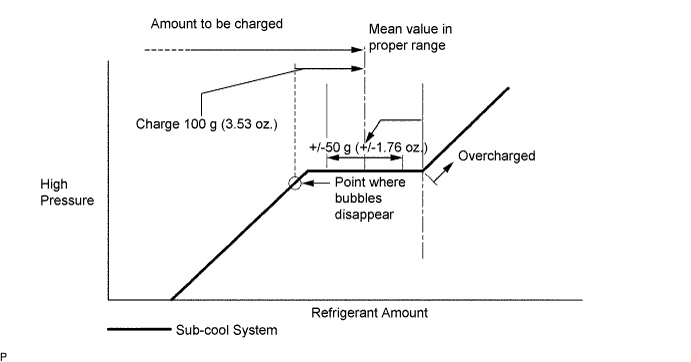
Note
-
Do not operate the cooler compressor before charging refrigerant as the cooler compressor will not work properly without any refrigerant, and will overheat.
-
Approximately 100 g (3.53 oz.) of refrigerant may need to be charged after bubbles disappear. The refrigerant amount should be checked by measuring its quantity, and not with the sight glass.
-
-
WARM UP ENGINE
-
Warm up the engine at less than 1850 rpm for 2 minutes or more after charging the refrigerant.
Note
Be sure to warm up the compressor when turning the A/C switch on after removing and installing the cooler refrigerant lines (including the compressor), to prevent damage to the compressor.
-
-
CHECK FOR ENGINE COOLANT LEAKS
-
Fill the radiator with coolant and attach a radiator cap tester.
-
Warm up the engine.
-
Using the radiator cap tester, increase the pressure inside the radiator to 123 kPa (1.3 kgf/cm2, 18 psi), and check that the pressure does not drop.
If the pressure drops, check the hoses, radiator and water pump for leaks. If no external leaks are found, check the heater core, cylinder block and head.
-
-
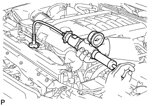
CHECK FOR REFRIGERANT GAS LEAK
-
After recharging the refrigerant gas, check for refrigerant gas leakage using a halogen leak detector.
-
Perform the operation under these conditions:
-
Stop the engine.
-
Secure good ventilation (the halogen leak detector may react to volatile gases other than refrigerant, such as evaporated gasoline or exhaust gas).
-
Repeat the test 2 or 3 times.
-
Make sure that some refrigerant remains in the refrigeration system. When compressor is off: approximately 392 to 588 kPa (4.0 to 6.0 kgf/cm2, 57 to 85 psi).
-
-
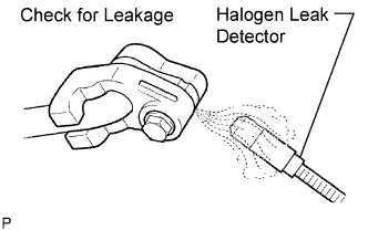
Using a halogen leak detector, check the refrigerant line for leakage.
-
If a gas leak is not detected on the drain hose, remove the blower motor control (blower resistor) from the cooling unit. Insert the halogen leak detector sensor into the unit and perform the test.
-
Disconnect the connector and wait for approximately 20 minutes. Bring the halogen leak detector close to the pressure switch and perform the test.
-
-
INSTALL UPPER RADIATOR SUPPORT SEAL
-
Install the upper radiator support seal with the 3 clips.
-
-
INSTALL ENGINE ROOM SIDE COVER LH
-
Install the engine room side cover LH with the 7 clips.
-
-
INSTALL ENGINE ROOM SIDE COVER RH
-
Install the engine room side cover RH with the 7 clips.
-
-
INSTALL NO. 1 ENGINE UNDER COVER SUB-ASSEMBLY
-
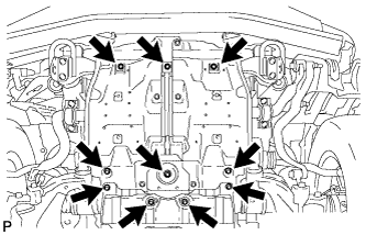
Install the No. 1 engine under cover with the 10 bolts.
- Torque:
- 29 N*m { 296 kgf*cm, 21 ft.*lbf }
-
-
INSTALL FRONT FENDER SPLASH SHIELD SUB-ASSEMBLY LH
-
Push in the clip to install the front fender splash shield sub-assembly LH.
-
Install the 3 bolts and 2 screws.
-
-
INSTALL FRONT FENDER SPLASH SHIELD SUB-ASSEMBLY RH
Tech Tips
Use the same procedure described for the LH side.