AIR CONDITIONING SYSTEM, Diagnostic DTC:B1461/61

| DTC Code | DTC Name |
|---|---|
| B1461/61 | Emission Gas NOx Sensor Circuit |
DESCRIPTION
The smog ventilation sensor, which is installed on the front of the cooler condenser assembly, automatically changes to fresh, fresh/recirculation or recirculation mode operation. The smog ventilation sensor detects NOx in the emission gas and transmits signals to the air conditioning amplifier assembly.
| DTC Code | DTC Detection Condition | Trouble Area |
|---|---|---|
| B1461/61 | An open or short in the smog ventilation sensor circuit (NOx). |
|
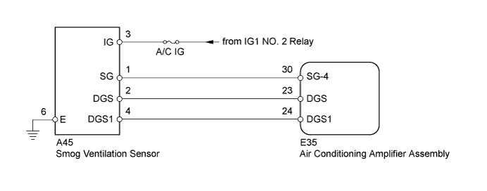
WIRING DIAGRAM
INSPECTION PROCEDURE
PROCEDURE
-
INSPECT FUSE (A/C IG)
-
Remove the A/C IG fuse from the cowl side junction block LH.
-
Measure the resistance according to the value(s) in the table below.
Standard Resistance Tester Connection Condition Specified Condition A/C IG fuse Always Below 1 Ω
NG 
REPLACE FUSE
OK 
-
-
READ VALUE USING INTELLIGENT TESTER (SMOG VENTILATION SENSOR)
-
Use the Data List to check if the smog ventilation sensor is functioning properly.
Air Conditioner Tester Display Measurement Item / Range Normal Condition Diagnostic Note Emission Gas Nox Sensor Smog ventilation sensor/
Min.: 0, Max.: 255
Increases as gas amount increases - OK The display is as specified in the normal condition.
NG 
CHECK HARNESS AND CONNECTOR (SMOG VENTILATION SENSOR - BODY GROUND) Click here
OK 
REPLACE AIR CONDITIONING AMPLIFIER ASSEMBLY Click here
-
-
CHECK HARNESS AND CONNECTOR (SMOG VENTILATION SENSOR - BODY GROUND)
-
Disconnect the A45 sensor connector.
-
Measure the resistance according to the value(s) in the table below.
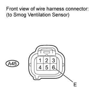
Standard Resistance Tester Connection Condition Specified Condition A45-6 (E) - Body ground Always Below 1 Ω
NG
REPAIR OR REPLACE HARNESS OR CONNECTOR
OK
-
-
CHECK HARNESS AND CONNECTOR (SMOG VENTILATION SENSOR - BATTERY)
-
Disconnect the A45 smog ventilation sensor connector.
-
Measure the voltage according to the value(s) in the table below.
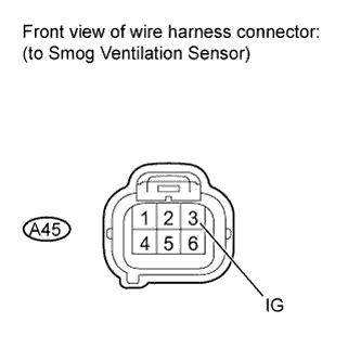
Standard Voltage Tester Connection Switch Condition Specified Condition A45-3 (IG) - Body ground Engine switch on (IG) 11 to 14 V
NG
REPAIR OR REPLACE HARNESS OR CONNECTOR
OK
-
-
INSPECT SMOG VENTILATION SENSOR
-
Remove the smog ventilation sensor Click here.
-
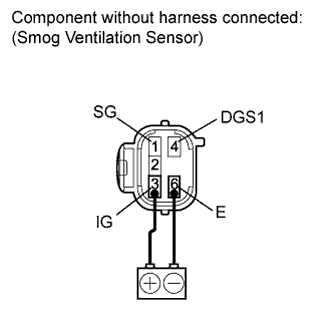
After applying battery voltage to terminals 3 (IG) and 6 (E) for more than 30 seconds, measure the resistance according to the value(s) in the table below.
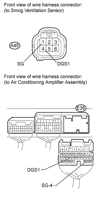
Standard Resistance Tester Connection Condition Specified Condition 1 (SG) - 4 (DGS1) 15 to 25°C
(59 to 77°F)
2.5 to 40 kΩ Tech Tips
When the sensor is exposed to the exhaust gas, the resistance increases.
NG
REPLACE SMOG VENTILATION SENSOR Click here
OK
-
-
CHECK HARNESS AND CONNECTOR (SMOG VENTILATION SENSOR - AIR CONDITIONING AMPLIFIER)
-
Disconnect the A45 smog ventilation sensor connector.
-
Disconnect the E35 amplifier connector.
-
Measure the resistance according to the value(s) in the table below.
Standard Resistance Tester Connection Condition Specified Condition A45-1 (SG) - E35-30 (SG-4) Always Below 1 Ω A45-4 (DGS1) - E35-24 (DGS1) E35-30 (SG-4) - Body ground Always 10 kΩ or higher E35-24 (DGS1) - Body ground
NG
REPAIR OR REPLACE HARNESS OR CONNECTOR
OK
REPLACE AIR CONDITIONING AMPLIFIER ASSEMBLY Click here
-