AIR CONDITIONING SYSTEM, Diagnostic DTC:B1419/19

| DTC Code | DTC Name |
|---|---|
| B1419/19 | Rear Room Temperature Sensor Circuit |
DESCRIPTION
The rear room temperature sensor LH*1 or RH*2 (for driver side) is installed in the rear quarter trim board LH*1 or RH*2 to detect the rear room temperature and control the heater and air conditioner auto mode. The resistance of the rear room temperature sensor LH*1 or RH*2 changes in accordance with the rear room temperature for the LH*1 or RH*2 seat. As the temperature decreases, the resistance increases. As the temperature increases, the resistance decreases.
The air conditioning amplifier assembly applies a voltage (5 V) to the rear room temperature sensor LH*1 or RH*2 and reads voltage changes as changes in the resistance of the rear room temperature sensor LH*1 or RH*2.
| DTC Code | DTC Detection Condition | Trouble Area |
|---|---|---|
| B1419/19 | An open or short in the rear room temperature sensor LH*1 or RH*2 circuit. |
|
-
*1: for LHD
-
*2: for RHD
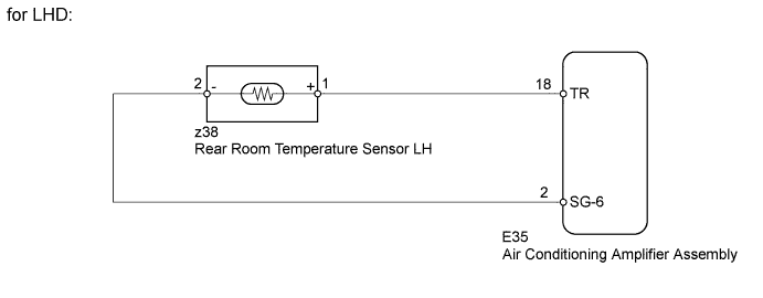
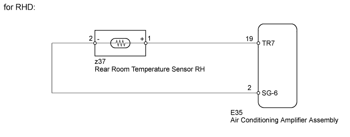
WIRING DIAGRAM
INSPECTION PROCEDURE
PROCEDURE
-
READ VALUE USING INTELLIGENT TESTER (REAR ROOM TEMPERATURE SENSOR)
-
Use the Data List to check if the rear room temperature sensor LH*1 or RH*2 is functioning properly.
Air Conditioner Tester Display Measurement Item/Range Normal Condition Diagnostic Note Room Temp Sensor (Rear) Rear room temperature sensor for LH*1 or RH*2 /
Min.: -6.5°C (20.3°F)
Max.: 57.25°C (135.05°F)
Actual rear room temperature for LH*1 or RH*2 displayed Open in the circuit: -6.5°C (20.3°F).
Short in the circuit: 57.25°C (135.05°F).
-
*1: for LHD
-
*2: for RHD
OK The display is as specified in the normal condition. -
NG 
INSPECT REAR ROOM TEMPERATURE SENSOR Click here
OK 
REPLACE AIR CONDITIONING AMPLIFIER ASSEMBLY Click here
-
-
INSPECT REAR ROOM TEMPERATURE SENSOR
-
Remove the rear room temperature sensor Click here.
-
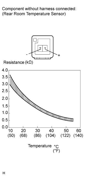
Measure the resistance according to the value(s) in the table below.
Standard Resistance Tester Connection Condition Specified Condition 1 (+) - 2 (-) 10°C (50°F) 3.00 to 3.73 kΩ 15°C (59°F) 2.45 to 2.88 kΩ 20°C (68°F) 1.95 to 2.30 kΩ 25°C (77°F) 1.60 to 1.80 kΩ 30°C (86°F) 1.28 to 1.47 kΩ 35°C (95°F) 1.00 to 1.22 kΩ 40°C (104°F) 0.80 to 1.00 kΩ 45°C (113°F) 0.65 to 0.85 kΩ 50°C (122°F) 0.50 to 0.70 kΩ 55°C (131°F) 0.44 to 0.60 kΩ 60°C (140°F) 0.36 to 0.50 kΩ Note
Even slightly touching the sensor may change the resistance value. Be sure to hold the connector of the sensor.
Tech Tips
As the temperature increases, the resistance decreases (See the graph).
NG 
REPLACE REAR ROOM TEMPERATURE SENSOR Click here
OK 
-
-
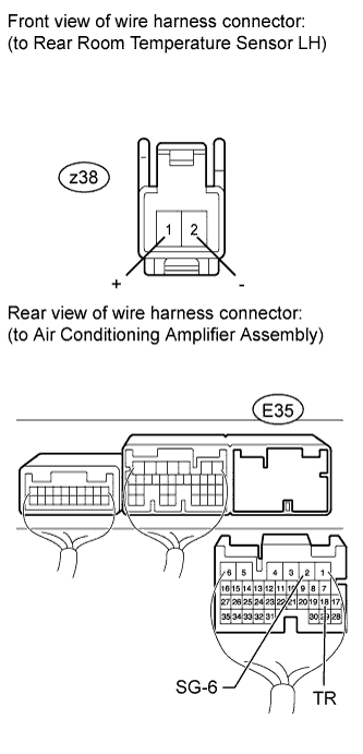
CHECK HARNESS AND CONNECTOR (REAR ROOM TEMPERATURE SENSOR - AIR CONDITIONING AMPLIFIER)
-
for LHD:
-
Disconnect the z38 sensor connector.
-
Disconnect the E35 amplifier connector.
-
Measure the resistance according to the value(s) in the table below.
Standard Resistance Tester Connection Condition Specified Condition z38-1 (+) - E35-18 (TR) Always Below 1 Ω z38-2 (-) - E35-2 (SG-6) E35-18 (TR) - Body ground Always 10 kΩ or higher E35-2 (SG-6) - Body ground
-
-
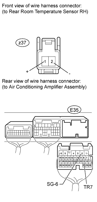
for RHD:
-
Disconnect the z37 sensor connector.
-
Disconnect the E35 amplifier connector.
-
Measure the resistance according to the value(s) in the table below.
Standard Resistance Tester Connection Condition Specified Condition z37-2 (-) - E35-2 (SG-6) Always Below 1 Ω z37-1 (+) - E35-19 (TR7) E35-2 (SG-6) - Body ground Always 10 kΩ or higher E35-19 (TR7) - Body ground
-
NG
REPAIR OR REPLACE HARNESS OR CONNECTOR
OK
REPLACE AIR CONDITIONING AMPLIFIER ASSEMBLY Click here
-