SEAT BELT CONTROL ECU (for LHD) REMOVAL

-
REMOVE ENGINE ROOM SIDE COVER LH
-
Remove the 7 clips and engine room side cover LH.
-
-
DISCONNECT CABLE FROM NEGATIVE BATTERY TERMINAL
CAUTION:
Wait at least 90 seconds after disconnecting the cable from the negative (-) battery terminal to disable the SRS system.
Note
-
When disconnecting the cable, some systems need to be initialized after the cable is reconnected Click here.
-
w/ Navigation System:
After the engine switch is turned off, the HDD navigation system requires approximately 6 minutes to record various types of memory and settings. As a result, after turning the engine switch off, wait 6 minutes or more before disconnecting the cable from the negative (-) battery terminal.
-
-
REMOVE LOWER INSTRUMENT PANEL PAD SUB-ASSEMBLY LH
-
Detach the 8 claws.
-
Disconnect the connector and remove the panel pad.
-
-
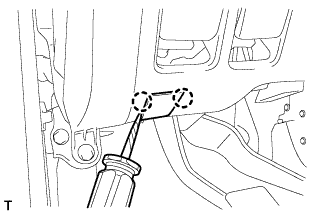
REMOVE INNER NO. 1 INSTRUMENT PANEL BRACKET COVER LH
-
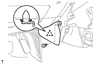
Remove the clip.
-
Detach the clip and remove the cover.
-
-
REMOVE INSTRUMENT SIDE PANEL LH
-
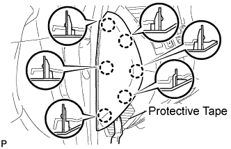
Place protective tape as shown in the illustration.
-
Using a moulding remover, detach the 6 claws and remove the side panel.
-
-
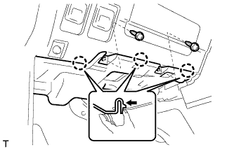
REMOVE NO. 1 SWITCH HOLE BASE
-
Detach the 5 claws.
-
Disconnect the connectors and remove the switch hole base.
-
-
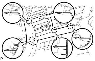
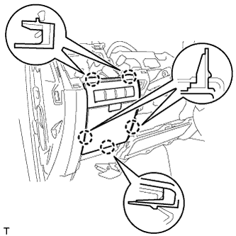
REMOVE NO. 1 INSTRUMENT PANEL UNDER COVER SUB-ASSEMBLY
-
Remove the 2 screws.
-
Detach the 3 claws.
-
Remove the under cover and disconnect the connectors.
-
-
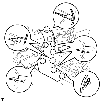
REMOVE LOWER NO. 1 INSTRUMENT PANEL FINISH PANEL
-
Using a screwdriver, detach the 2 claws and open the hole cover.
Tech Tips
Tape the screwdriver tip before use.
-
Remove the 2 bolts.
-
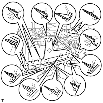
Detach the 16 claws.
-
Detach the 2 claws and remove the sensor.
-
Detach the 2 claws and disconnect the 2 control cables.
-
Remove the finish panel and then disconnect the connectors.
-
-
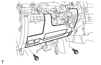
REMOVE INSTRUMENT PANEL BOX ASSEMBLY
-
Detach the 5 claws.
-
Remove the box and then disconnect the connectors.
-
-
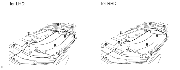
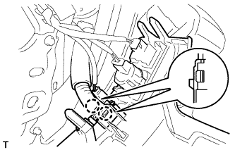
REMOVE DRIVER SIDE KNEE AIRBAG ASSEMBLY
-
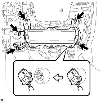
Remove the 5 bolts and driver side knee airbag.
-
Disconnect the connector.
Note
When handling the airbag connector, take care not to damage the airbag wire harness.
-
-
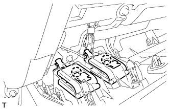
REMOVE SEAT BELT CONTROL ECU
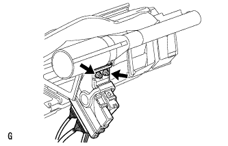
-
Disconnect the connectors.
-
Remove the 2 nuts and seat belt control ECU.
-
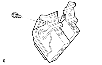
Remove the bolt and seat belt control ECU.
-