PRE-CRASH SAFETY SYSTEM Power Source Circuit
DESCRIPTION
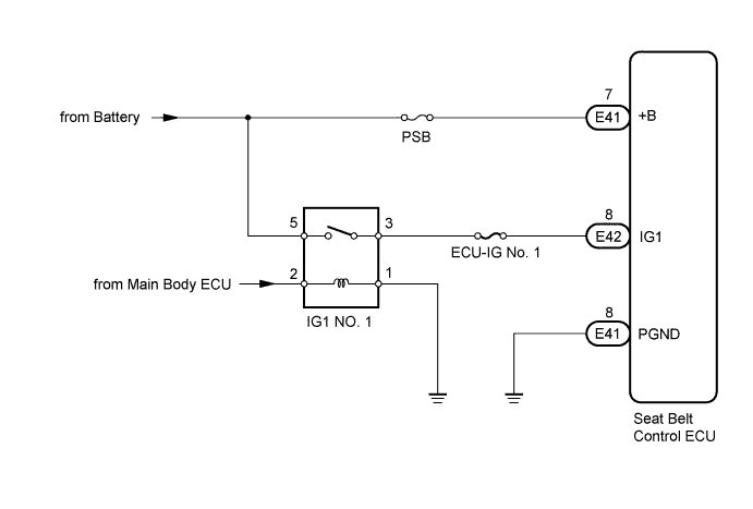
This circuit supplies power to the seat belt control ECU when the engine switch is on (IG).
WIRING DIAGRAM
INSPECTION PROCEDURE
Tech Tips
Start the engine before inspection. Check the IG1 NO. 1 relay or battery if the starting system does not start.
PROCEDURE
-
INSPECT FUSE (ECU-IG No. 1, PSB)
-
Remove the ECU-IG No. 1 and PSB fuses from the cowl side junction block LH.
-
Measure the resistance according to the value(s) in the table below.
Standard Resistance Tester Connection Condition Specified Condition ECU-IG No. 1 fuse Always Below 1 Ω PSB fuse
NG 
REPLACE FUSE
OK 
-
-
CHECK HARNESS AND CONNECTOR (SEAT BELT CONTROL ECU - BATTERY AND BODY GROUND)
-
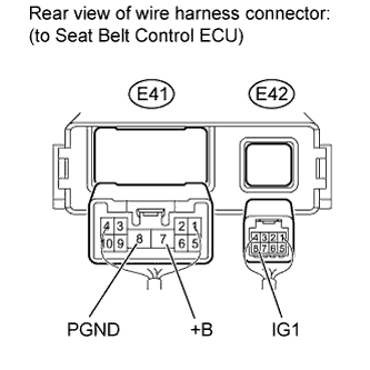
Disconnect the E41 and E42 seat belt control ECU connectors.
-
Measure the voltage according to the value(s) in the table below.
Standard Voltage Tester Connection Switch Condition Specified Condition E42-8 (IG1) - Body ground Engine switch on (IG) 11 to 14 V Engine switch off Below 1 V E41-7 (+B) - Body ground Always 11 to 14 V -
Measure the resistance according to the value(s) in the table below.
Standard Resistance Tester Connection Condition Specified Condition E41-8 (PGND) - Body ground Always Below 1 Ω Result Result Proceed to OK
(for LHD)
A OK
(for RHD)
B NG C
B
REPLACE SEAT BELT CONTROL ECU Click here
C
REPAIR OR REPLACE HARNESS OR CONNECTOR
A 
REPLACE SEAT BELT CONTROL ECU Click here
-