METER / GAUGE SYSTEM Meter Illumination does not Dim at Night
DESCRIPTION
If the dimmer switch is turned to tail, head or AUTO, the main body ECU sends a TAIL relay signal, panel light illumination signal, panel relay signal, and TAIL cancel OFF signal to the combination meter. Then the meter and accessory meter become dim.
Tech Tips
TAIL cancel switch: When the headlights are illuminated and the TAIL cancel switch is turned off, the meter does not dim.
WIRING DIAGRAM
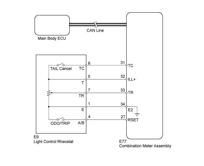
INSPECTION PROCEDURE
PROCEDURE
-
CHECK CAN COMMUNICATION SYSTEM
-
Check for DTCs Click here.
Result Result Proceed to CAN communication system DTC is not output A CAN communication system (for LHD) DTC is output B CAN communication system (for RHD) DTC is output C
B 
Go to CAN COMMUNICATION SYSTEM Click here
C
Go to CAN COMMUNICATION SYSTEM Click here
A 
-
-
READ VALUE USING INTELLIGENT TESTER (LIGHT CONTROL RHEOSTAT)
-
Operate the intelligent tester according to the display and select the Data List Click here.
Combination Meter Tester Display Measurement Item/Range Normal Condition Diagnostic Note Tail Cancel SW TAIL cancel switch condition/ON or OFF ON: TAIL cancel switch on
OFF: TAIL cancel switch off
- Rheostat value Light control rheostat switch input/Min.: 0, Max.: 100 Light control rheostat switch is fully turned left (0) → fully turned right (100) Unit: % OK Light brightness can be changed within specified range by manual operation.
NG
REPLACE COMBINATION METER ASSEMBLY Click here
OK
-
-
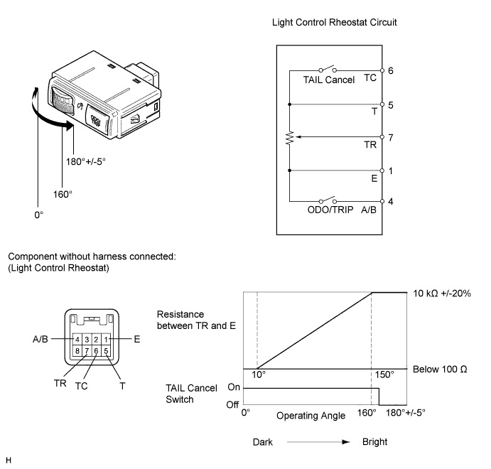
INSPECT LIGHT CONTROL RHEOSTAT
-
Inspect the light control rheostat.
-
Remove the light control rheostat Click here.
-
Measure the resistance according to the value(s) in the table below.
Standard Resistance Tester Connection Switch Condition Specified Condition 6 (TC) - 5 (T) TAIL cancel switch off → on 10 kΩ or higher → Below 1 Ω 5 (T) - 1 (E) Always 10 kΩ +/-20% 7 (TR) - 1 (E) Light control rheostat fully turned right → fully turned left 10 kΩ +/-20% → Below 100 Ω
-
NG
REPLACE LIGHT CONTROL RHEOSTAT Click here
OK
-
-
CHECK HARNESS AND CONNECTOR (COMBINATION METER - LIGHT CONTROL RHEOSTAT AND BODY GROUND)
-
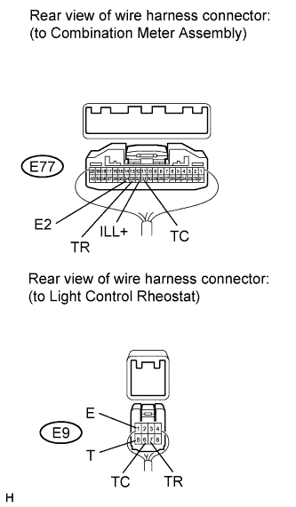
Disconnect the E77 meter connector.
-
Disconnect the E9 rheostat connector.
-
Measure the resistance according to the value(s) in the table below.
Standard Resistance Tester Connection Condition Specified Condition E77-32 (ILL+) - E9-5 (T) Always Below 1 Ω E77-33 (TR) - E9-7 (TR) E77-34 (E2) - E9-1 (E) E77-31 (TC) - E9-6 (TC) E77-32 (ILL+) or E9-5 (T) - Body ground Always 10 kΩ or higher E77-33 (TR) or E9-7 (TR) - Body ground E77-34 (E2) or E9-1 (E) - Body ground E77-31 (TC) or E9-6 (TC) - Body ground
NG
REPAIR OR REPLACE HARNESS OR CONNECTOR
OK 
REPLACE COMBINATION METER ASSEMBLY Click here
-