LIGHT CONTROL RHEOSTAT INSPECTION

-
INSPECT LIGHT CONTROL RHEOSTAT
-
Inspect the light control rheostat.
-
Measure the resistance according to the value(s) in the table below.
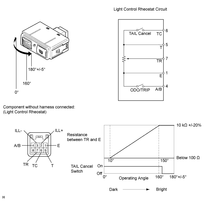
Standard Resistance Tester Connection Switch Condition Specified Condition 6 (TC) - 5 (E) TAIL cancel switch off → on 10 kΩ or higher → Below 1 Ω 5 (T) - 1 (E) Always 10 kΩ +/-20% 7 (TR) - 1 (E) Light control rheostat fully turned right → Light control rheostat fully turned left 10 kΩ +/-20% → Below 100 Ω
-
-
Inspect the ODO/TRIP switch.
-
Measure the resistance according to the value(s) in the table below.
Standard Resistance Tester Connection Switch Condition Specified Condition 4 (A/B) - 1 (E) ODO/TRIP switch on (Pushed) Below 100 Ω ODO/TRIP switch off (Not pushed) 1 MΩ or higher
-
-
Apply battery voltage to the connector and check the LED illumination condition.
OK Measurement Condition Specified Condition Battery positive (+) → Terminal 2 (ILL+)
Battery negative (-) → Terminal 3 (ILL-)
LED illuminates If the result is not as specified, replace the rheostat.
-