THEFT DETERRENT SYSTEM IG Power Source Circuit
DESCRIPTION
-
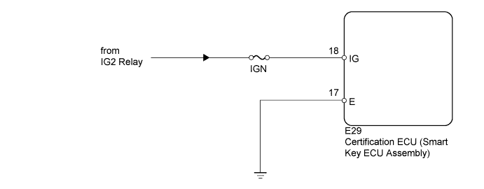
When the engine switch is turned on (IG), positive (+) battery voltage is applied to the certification ECU (smart key ECU assembly).
WIRING DIAGRAM
INSPECTION PROCEDURE
PROCEDURE
-
CHECK BASIC FUNCTION (POWER SOURCE MODE FUNCTION)
-
Check the basic function of the power source mode function.
OK Basic function operates normally.
NG 
GO TO ENTRY AND START SYSTEM (for Start Function) Click here
OK 
-
-
INSPECT FUSE (IGN)
-
Remove the IGN fuse from the engine room relay block.
-
Measure the resistance according to the value(s) in the table below.
Standard Resistance Tester Connection Condition Specified Condition IGN fuse Always Below 1 Ω
NG
REPLACE FUSE
OK
-
-
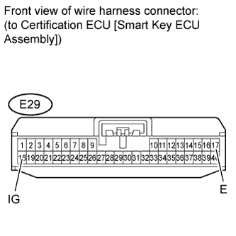
CHECK HARNESS AND CONNECTOR (CERTIFICATION ECU [SMART KEY ECU ASSEMBLY] - BATTERY AND BODY GROUND)
-
Disconnect the E29 ECU connector.
-
Measure the resistance according to the value(s) in the table below.
Standard Resistance Tester Connection Condition Specified Condition E29-17 (E) - Body ground Always Below 1 Ω -
Measure the voltage according to the value(s) in the table below.
Standard Voltage Tester Connection Switch Condition Specified Condition E29-18 (IG) - Body ground Engine switch on (IG) 11 to 14 V
NG
REPAIR OR REPLACE HARNESS OR CONNECTOR
OK 
PROCEED TO NEXT CIRCUIT INSPECTION SHOWN IN PROBLEM SYMPTOMS TABLE Click here
-