THEFT DETERRENT SYSTEM Security Horn Circuit
DESCRIPTION
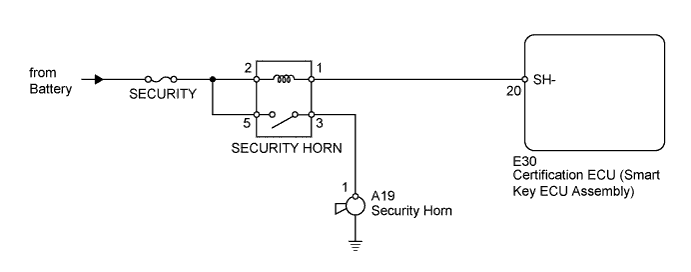
When the theft deterrent system is operating, the certification ECU (smart key ECU assembly) outputs a signal continuously at 0.4 second intervals, causing the security horn to sound.
WIRING DIAGRAM
INSPECTION PROCEDURE
PROCEDURE
-
PERFORM ACTIVE TEST USING INTELLIGENT TESTER (SECURITY HORN)
-
Operate the intelligent tester according to the steps on the display and select "Active Test".
Entry&Start Tester Display Test Part Control Range Diagnostic Note Security Horn Security horn ON/OFF - OK Security horn operates normally.
NG 
INSPECT FUSE (SECURITY) Click here
OK 
REPLACE CERTIFICATION ECU (SMART KEY ECU ASSEMBLY)
-
-
INSPECT FUSE (SECURITY)
-
Remove the SECURITY fuse from the engine room relay block.
-
Measure the resistance according to the value(s) in the table below.
Standard Resistance Tester Connection Condition Specified Condition SECURITY fuse Always Below 1 Ω
NG 
REPLACE FUSE
OK 
-
-
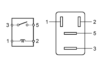
INSPECT SECURITY HORN RELAY
-
Remove the security horn relay from the engine room relay block.
-
Measure the resistance according to the value(s) in the table below.
Standard Resistance Tester Connection Condition Specified Condition 3 - 5 Battery voltage is not applied to terminals 1 and 2 10 kΩ or higher 3 - 5 Battery voltage is applied to terminals 1 and 2 Below 1 Ω
NG
REPLACE SECURITY HORN RELAY
OK
-
-
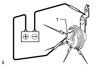
INSPECT SECURITY HORN ASSEMBLY
-
Remove the security horn Click here.
-
Apply battery voltage to the horn and check the operation of the horn.
OK Measurement Condition Specified Condition Battery positive (+) → Terminal 1
Battery negative (-) → Horn bracket
Horn sounds
NG
REPLACE SECURITY HORN ASSEMBLY Click here
OK
-
-
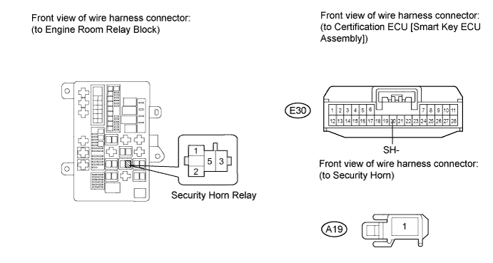
CHECK HARNESS AND CONNECTOR (ENGINE ROOM RELAY BLOCK - CERTIFICATION ECU [SMART KEY ECU ASSEMBLY] AND SECURITY HORN)
-
Remove the security horn relay from the engine room relay block.
-
Disconnect the E30 ECU connector.
-
Disconnect the A19 horn connector.
-
Measure the resistance according to the value(s) in the table below.
Standard Resistance Tester Connection Condition Specified Condition Relay block security horn relay terminal 1 - E30-20 (SH-) Always Below 1 Ω Relay block security horn relay terminal 3 - A19-1 Always Below 1 Ω E30-20 (SH-) Body ground Always 10 kΩ or higher A19-1 - Body ground Always 10 kΩ or higher -
Measure the voltage according to value(s) in the table below.
Standard Voltage Tester Connection Condition Specified Condition Relay block security horn relay terminal 2 - Body ground Always 11 to 14 V Relay block security horn relay terminal 5 - Body ground Always 11 to 14 V
NG
REPAIR OR REPLACE HARNESS OR CONNECTOR
OK
REPLACE CERTIFICATION ECU (SMART KEY ECU ASSEMBLY)
-