ENTRY LOCK AND UNLOCK SWITCH (for Front) INSTALLATION

Tech Tips
-
Use the same procedures for the LH side and RH side.
-
The procedures listed below are for the LH side.
-
INSTALL FRONT DOOR HANDLE ASSEMBLY OUTSIDE LH
-
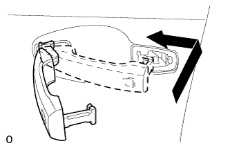
Install the handle by pushing it in the direction of the arrow in the illustration.
-
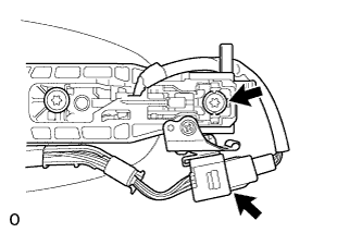
Using a T30 "TORX" socket, tighten the screw.
-
Connect the connector.
-
-
INSTALL FRONT DOOR OUTSIDE HANDLE COVER LH
-
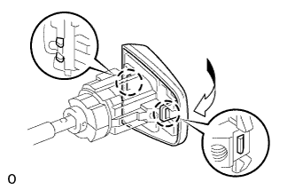
Attach the 2 claws to install the front door outside handle cover LH to the front door lock cylinder.
-
Using a T30 "TORX" socket, install the front door outside handle cover LH (with the door lock cylinder) with the screw.
- Torque:
- 4.0 N*m { 41 kgf*cm, 35 in.*lbf }
-
Install the hole plug.
-
-
INSTALL FRONT DOOR SERVICE HOLE COVER LH
-
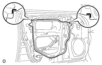
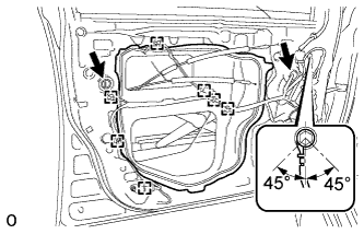
Apply butyl tape to the door.
-
Pass the front door lock remote control cable assembly LH and front door inside locking cable assembly LH through a new front door service hole cover LH.
Note
-
When installing the front door service hole cover LH, pull the links and connectors through the front door service hole cover LH.
-
There should be no wrinkles or folds after installing the front door service hole cover LH.
-
After installing the front door service hole cover LH, check the sealing quality.
-
-
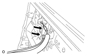
Connect the 2 connectors.
-
Attach the 7 clamps.
-
Install the bolt as shown in the illustration.
- Torque:
- 8.4 N*m { 86 kgf*cm, 74 in.*lbf }
-
-
INSTALL DOOR TRIM COVER LH
-
Attach the 7 clips to install the door trim cover LH.
-
-
INSTALL FRONT NO. 1 DOOR STIFFENER CUSHION
-
Install the front No. 1 door stiffener cushion with the screw.
-
-
INSTALL FRONT DOOR TRIM BOARD SUB-ASSEMBLY LH
-
Connect the connector.
-
Connect the front door lock remote control cable assembly LH and front door inside locking cable assembly LH to the front door inside handle sub-assembly LH.
-
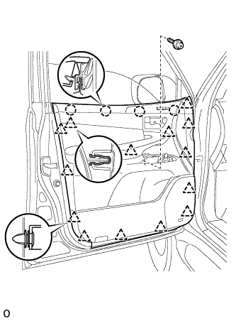
Attach the 4 claws and 14 clips to install the front door trim board sub-assembly LH.
-
Install the 2 screws.
-
-
INSTALL FRONT UPPER ARMREST BASE PANEL LH
-
Connect the connector.
-
Attach the 5 claws to install the front upper armrest base panel LH.
-
-
INSTALL FRONT DOOR INSIDE HANDLE BEZEL PLUG LH
-
Attach the 3 claws to install the front door inside handle bezel plug LH.
-
-
INSTALL COURTESY LIGHT ASSEMBLY
-
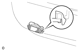
Connect the connector.
-
Attach the claw of the courtesy light to the front door trim.
-
-
INSTALL FRONT LOWER DOOR FRAME BRACKET GARNISH LH
-
Attach the clip and claw to install the front lower door frame bracket garnish LH.
-
-
CONNECT CABLE TO NEGATIVE BATTERY TERMINAL
Note
When disconnecting the cable, some systems need to be initialized after the cable is reconnected Click here.
-
CHECK SRS WARNING LIGHT
-
Check the SRS warning light Click here.
-
-
INSTALL ENGINE ROOM SIDE COVER LH
-
Install the engine room side cover LH with the 7 clips.
-