ENTRY AND START SYSTEM (for Start Function) Engine Switch Indicator Circuit
DESCRIPTION
The engine switch condition (power source mode) or system malfunctions can be checked by observing the status of the engine switch indicator light.
| Power Source Mode/Condition | Indicator Light Condition | |
|---|---|---|
| Brake Pedal Released | Brake Pedal Depressed, Shift Lever in P | |
| Off | Off | Illuminates (green) |
| On (ACC), on (IG) | Illuminates (amber) | Illuminates (green) |
| Engine running | Off | Off |
| Steering lock not unlocked | Flashes (green) for 30 seconds | Flashes (green) for 30 seconds |
| System malfunction | Flashes (amber) for 15 seconds | Flashes (amber) for 15 seconds |
| Stop light switch malfunction with shift lever in P | Flashes (green) for 15 seconds | Flashes (green) for 15 seconds |
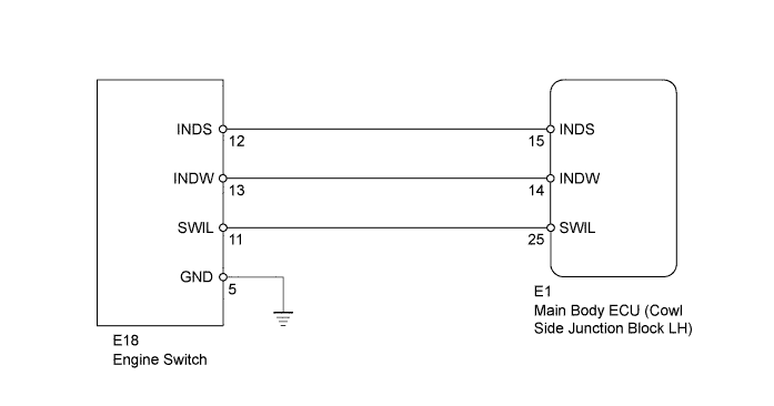
WIRING DIAGRAM
INSPECTION PROCEDURE
PROCEDURE
-
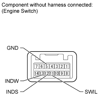
INSPECT ENGINE SWITCH
-
Disconnect the E18 engine switch connector.
-
Apply battery voltage to the terminals of the engine switch, and check the illumination condition of the engine switch indicator light.
Note
-
If the positive (+) lead and the negative (-) lead are incorrectly connected, the engine switch indicator light will not illuminate.
-
If the voltage is too low, the indicator light will not illuminate.
OK Measurement Condition Condition Specified Condition Battery terminal (+) → Terminal 11 (SWIL) - Battery terminal (-) → Terminal 5 (GND) Battery voltage is applied to the terminals Illuminates Battery terminal (+) → Terminal 12 (INDS) - Battery terminal (-) → Terminal 5 (GND) Battery terminal (+) → Terminal 13 (INDW) - Battery terminal (-) → Terminal 5 (GND) Result Result Proceed to OK A NG (for 3UR-FE) B NG (for 1UR-FE) C -
B 
REPLACE ENGINE SWITCH Click here
C
REPLACE ENGINE SWITCH Click here
A 
-
-
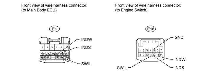
CHECK HARNESS AND CONNECTOR (ENGINE SWITCH - MAIN BODY ECU AND BODY GROUND)
-
Disconnect the E1 main body ECU connector.
-
Disconnect the E18 engine switch connector.
-
Measure the resistance according to the value(s) in the table below.
Standard Resistance Tester Connection Condition Specified Condition E1-25 (SWIL) - E18-11 (SWIL) Always Below 1 Ω E1-15 (INDS) - E18-12 (INDS) Always Below 1 Ω E1-14 (INDW) - E18-13 (INDW) Always Below 1 Ω E18-5 (GND) - Body ground Always Below 1 Ω E1-25 (SWIL) or E18-11 (SWIL) - Body ground Always 10 kΩ or higher E1-15 (INDS) or E18-12 (INDS) - Body ground Always 10 kΩ or higher E1-14 (INDW) or E18-13 (INDW) - Body ground Always 10 kΩ or higher
NG
REPAIR OR REPLACE HARNESS OR CONNECTOR
OK 
REPLACE MAIN BODY ECU (COWL SIDE JUNCTION BLOCK LH)
-