ENTRY AND START SYSTEM (for Start Function) Engine does not Start
DESCRIPTION
-
ENGINE START SYSTEM OPERATION
-
When the engine switch is pressed with the brake pedal depressed and the shift lever in P, the main body ECU determines that it is an engine start request.
-
The certification ECU (smart key ECU assembly) and other ECUs perform key verification via the LIN communication line. The engine switch indicator light illuminates in green.
-
The main body ECU activates the IG1 No. 3 relay, ACC relay and integration relay (IG2 relay).
-
The certification ECU (smart key ECU assembly) outputs a steering unlock signal. The signal is sent to the steering lock ECU via the LIN communication line.
-
The main body ECU sends an engine start request signal to the ECM.
-
The main body ECU deactivates the ACC relay until the ECU detects an engine start.
-
The ECU reactivates the ACC relay and turns off the engine switch indicator light.
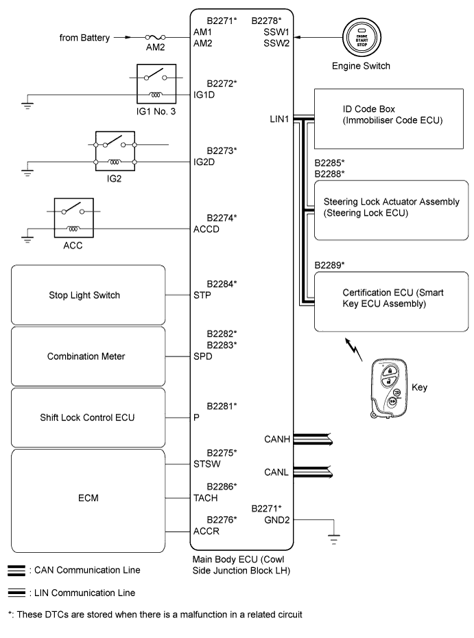
Symbols of Main Body ECU Signals SSW1/SSW2 Engine switch on (ACC), on (IG) signal IG1D IG1 No. 3 relay operation signal ACCD ACC relay operation signal IG2D Integration relay (IG2 relay) operation signal STP Stop light switch signal P Shift lock signal TACH Engine start detection signal STSW Starter activation request signal ACCR ACC cut request signal
-
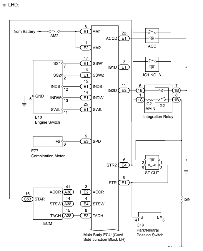
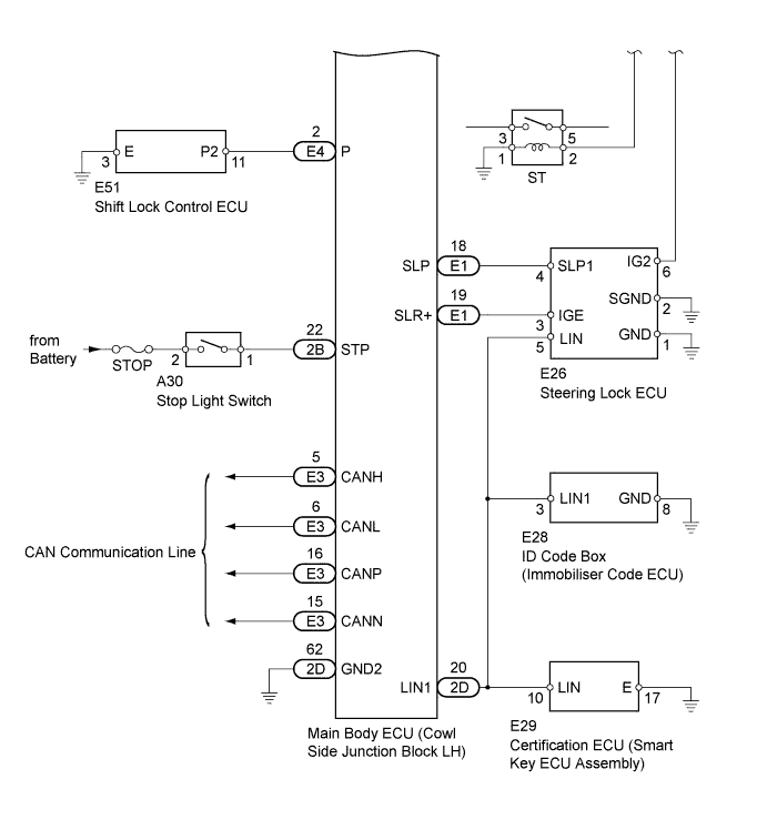
WIRING DIAGRAM

INSPECTION PROCEDURE
PROCEDURE
-
CHECK ENGINE SWITCH (SWITCH CONDITION)
-
Check the power source mode change.
-
When the key is inside the vehicle and the shift lever is in P, check that pressing the engine switch causes the power source mode to change as follows:
OK off → on (ACC) → on (IG) → off
-
NG 
GO TO ENTRY AND START SYSTEM (FOR START FUNCTION) (POWER SOURCE MODE DOES NOT CHANGE) Click here
OK 
-
-
CHECK WHETHER DTC OUTPUT RECURS
-
Clear the DTCs Click here.
-
Check whether the trouble recurs 5 seconds after the engine switch is turned on (IG).
-
Check whether DTCs for the main body ECU or certification ECU (smart key ECU assembly) are output.
Result Result Proceed to No DTC output A DTC for main body ECU output
Entry and start system (for start function)
B DTC for certification ECU (Smart key ECU assembly) output
Steering lock system
C DTC for certification ECU (Smart key ECU assembly) output
Engine immobiliser system
D
B
GO TO ENTRY AND START SYSTEM (FOR START FUNCTION) (DIAGNOSTIC TROUBLE CODE CHART) Click here
C
GO TO STEERING LOCK SYSTEM (DIAGNOSTIC TROUBLE CODE CHART) Click here
D
GO TO ENGINE IMMOBILISER SYSTEM (DIAGNOSTIC TROUBLE CODE CHART) Click here
A
-
-
CHECK CRANKING FUNCTION
-
Check the engine cranking function.
-
When there is fuel in the fuel tank, the key is inside the vehicle and the shift lever is in P, check that depressing the brake pedal and pressing the engine switch cranks the engine.
OK Engine cranks.
-
NG 
READ VALUE USING INTELLIGENT TESTER (SHIFT LOCK CONTROL ECU) Click here
OK
-
-
READ VALUE USING INTELLIGENT TESTER (L CODE)
-
Use the Data List to check if L code certification is functioning properly.
Entry and Start Tester Display Measurement Item/Range Normal Condition Diagnostic Note L Code Check L code certification result/NG or OK OK: L code certification result normal
NG: L code certification result abnormal
- OK OK is displayed on the intelligent tester.
NG
REPLACE STEERING LOCK ECU (STEERING LOCK ACTUATOR ASSEMBLY) Click here
OK
-
-
READ VALUE USING INTELLIGENT TESTER (ENGINE START CONDITION)
-
Use the Data List to check if the engine start is functioning properly.
Entry and Start Tester Display Measurement Item/Range Normal Condition Diagnostic Note Engine Start Condition Engine start condition by certification ECU (smart key ECU assembly)/OK or NG OK: Engine start permitted
NG: Engine start prohibited
- OK OK is displayed on the intelligent tester.
NG
REPLACE CERTIFICATION ECU (SMART KEY ECU ASSEMBLY) Click here
OK
-
-
READ VALUE USING INTELLIGENT TESTER (S CODE)
-
Use the Data List to check if S code certification is functioning properly.
Entry and Start Tester Display Measurement Item/Range Normal Condition Diagnostic Note S Code Check S code certification result/NG or OK OK: S code certification result normal
NG: S code certification result abnormal
- OK OK is displayed on the intelligent tester.
NG
REPLACE CERTIFICATION ECU (SMART KEY ECU ASSEMBLY) Click here
OK
-
-
REPLACE ID CODE BOX (IMMOBILISER CODE ECU)
-
Replace the ID code box (immobiliser code ECU).
-
Register the recognition code (ECU code).
-
Check that the engine starts.
OK Engine starts. Result Result Proceed to OK A NG (for 3UR-FE) B NG (for 1UR-FE) C
B
REPLACE ECM Click here
C
REPLACE ECM Click here
A 
END
-
-
READ VALUE USING INTELLIGENT TESTER (SHIFT LOCK CONTROL ECU)
-
Use the Data List to check if the shift position signal is functioning properly.
Main Body Tester Display Measurement Item/Range Normal Condition Diagnostic Note Shift P Signal Shift P position signal/ON or OFF ON: Shift lever in P
OFF: Shift lever not in P
- OK ON (shift lever in P) and OFF (shift lever not in P) are displayed on the intelligent tester.
NG
CHECK HARNESS AND CONNECTOR (SHIFT LOCK CONTROL ECU - MAIN BODY ECU AND BODY GROUND) Click here
OK
-
-
READ VALUE USING INTELLIGENT TESTER (PARK/NEUTRAL POSITION SWITCH)
-
Use the Data List to check if the park/neutral switch is functioning properly.
Main Body Tester Display Measurement Item/Range Normal Condition Diagnostic Note Neutral SW/ Clutch SW Park/neutral position switch/ON or OFF ON: Shift lever in P or N
OFF: Shift lever not in P or N
- OK ON (shift lever in P or N) and OFF (shift lever not in P or N) are displayed on the intelligent tester.
NG
INSPECT STARTER RELAY (ST) Click here
OK
-
-
READ VALUE USING INTELLIGENT TESTER (STOP LIGHT SWITCH)
-
Use the Data List to check if the stop light switch is functioning properly.
Main Body Tester Display Measurement Item/Range Normal Condition Diagnostic Note Stop Light SW Stop light switch/ON or OFF ON: Brake pedal depressed
OFF: Brake pedal released
- OK ON (brake pedal is depressed) and OFF (brake pedal is released) are displayed on the intelligent tester.
NG
INSPECT FUSE (STOP) Click here
OK
-
-
CHECK STEERING LOCK
-
Check if the steering lock is released when turning the engine switch on (ACC).
OK The steering lock is released.
NG
GO TO STEERING LOCK SYSTEM (HOW TO PROCEED WITH TROUBLESHOOTING) Click here
OK
-
-
CHECK MAIN BODY ECU (COWL SIDE JUNCTION BLOCK LH)
-
Measure the voltage according to the value(s) in the table below.
Tech Tips
The voltage is generated at terminal STSW for 0.3 seconds when the engine cranks.
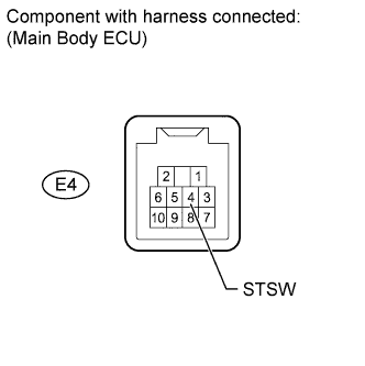
Standard Voltage Tester Connection Condition Specified Condition E4-4 (STSW) - Body ground Brake pedal depressed with shift lever in P, engine switch pushed once 11 to 14 V Result Result Proceed to OK (for 3UR-FE) A OK (for 1UR-FE) B NG C
B
REPLACE ECM Click here
C
REPLACE MAIN BODY ECU (COWL SIDE JUNCTION BLOCK LH)
A
REPLACE ECM Click here
-
-
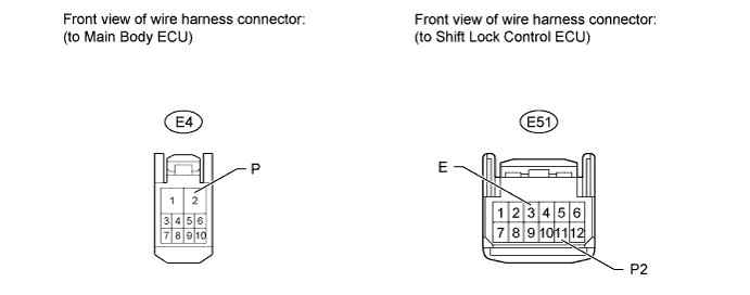
CHECK HARNESS AND CONNECTOR (SHIFT LOCK CONTROL ECU - MAIN BODY ECU AND BODY GROUND)
-
Disconnect the E4 main body ECU connector.
-
Disconnect the E51 shift lock control ECU connector.
-
Measure the resistance according to the value(s) in the table below.
Standard Resistance Tester Connection Condition Specified Condition E4-2 (P) - E51-11 (P2) Always Below 1 Ω E51-3 (E) - Body ground Always Below 1 Ω E4-2 (P) or E51-11 (P2) - Body ground Always 10 kΩ or higher
NG
REPAIR OR REPLACE HARNESS OR CONNECTOR
OK
-
-
INSPECT SHIFT LOCK CONTROL ECU SUB-ASSEMBLY
-
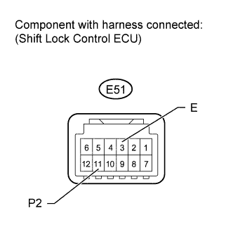
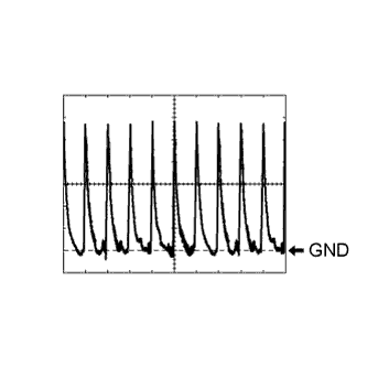
Check the signal waveform according to the condition(s) in the table below.
Reference Terminal No. (Symbol) Tool Setting Condition E51-11 (P2) - E51-3 (E) 2 V/DIV., 20 msec./DIV. Shift lever in P OK The waveform is similar to that shown in the illustration.
NG
REPLACE SHIFT LOCK CONTROL ECU SUB-ASSEMBLY Click here
OK
REPLACE MAIN BODY ECU (COWL SIDE JUNCTION BLOCK LH)
-
-
INSPECT STARTER RELAY (ST)
-
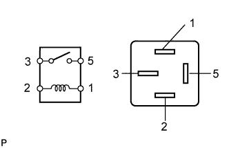
Remove the starter relay from the engine room relay block.
-
Measure the resistance according value(s) in the table below.
Standard Resistance Tester Connection Condition Specified Condition 3 - 5 Battery voltage not applied to terminals 1 and 2 10 kΩ or higher 3 - 5 Battery voltage applied to terminals 1 and 2 Below 1 Ω
NG
REPLACE STARTER RELAY
OK
-
-
INSPECT PARK/NEUTRAL POSITION SWITCH ASSEMBLY
-
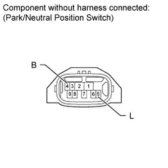
Disconnect the C19 park/neutral position switch connector.
-
Measure the resistance according to the value(s) in the table below.
Standard Resistance Tester Connection Switch Condition Specified Condition 4 (B) - 5 (L) P Below 1 Ω 4 (B) - 5 (L) N Below 1 Ω 4 (B) - 5 (L) Not in P or N 10 kΩ or higher
NG
REPLACE PARK/NEUTRAL POSITION SWITCH ASSEMBLY Click here
OK
-
-
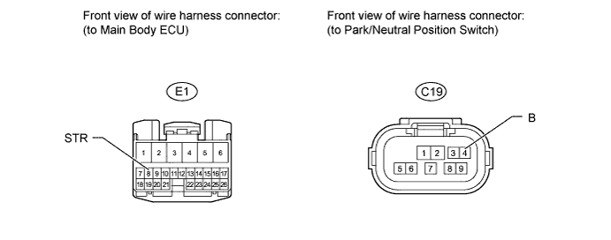
CHECK HARNESS AND CONNECTOR (MAIN BODY ECU - PARK/NEUTRAL POSITION SWITCH)
-
Measure the resistance according to the value(s) in the table below.
Standard Resistance Tester Connection Condition Specified Condition E1-8 (STR) - C19-4 (B) Always Below 1 Ω E1-8 (STR) or C19-4 (B) - Body ground Always 10 kΩ or higher
NG
REPLACE SHIFT LOCK CONTROL ECU SUB-ASSEMBLY Click here
OK
-
-
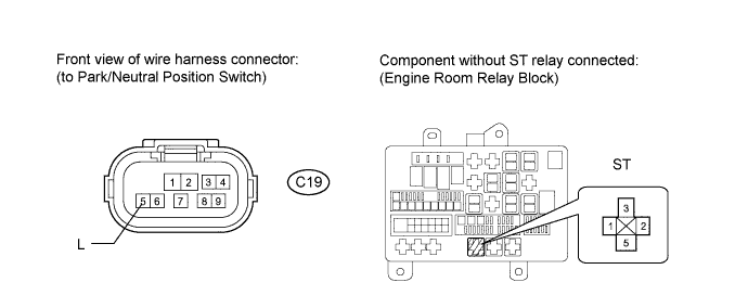
CHECK HARNESS AND CONNECTOR (STARTER RELAY - PARK/NEUTRAL POSITION SWITCH AND BODY GROUND)
-
Measure the resistance according to the value(s) in the table below.
Standard Resistance Tester Connection Condition Specified Condition C19-5 (L) - Relay block ST relay terminal 2 Always Below 1 Ω C19-5 (L) or Relay block ST relay terminal 2- Body ground Always 10 kΩ or higher Relay block ST relay terminal 1 - Body ground Always Below 1 Ω
NG
REPLACE SHIFT LOCK CONTROL ECU SUB-ASSEMBLY Click here
OK
REPLACE MAIN BODY ECU (COWL SIDE JUNCTION BLOCK LH)
-
-
INSPECT FUSE (STOP)
-
Remove the STOP fuse from the engine room relay block.
-
Measure the resistance according to the value(s) in the table below.
Standard Resistance Tester Connection Condition Specified Condition STOP fuse Always Below 1 Ω
NG
REPLACE FUSE
OK
-
-
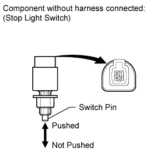
INSPECT STOP LIGHT SWITCH ASSEMBLY
-
Disconnect the A30 stop light switch connector.
-
Measure the resistance according to the value(s) in the table below.
Standard Resistance Tester Connection Switch Condition Specified Condition 1 - 2 Stop light switch pin not pushed Below 1 Ω 3 - 4 Stop light switch pin pushed Below 1 Ω 1 - 2 Stop light switch pin pushed 10 kΩ or higher 3 - 4 Stop light switch pin not pushed 10 kΩ or higher
NG
REPLACE STOP LIGHT SWITCH ASSEMBLY Click here
OK
-
-
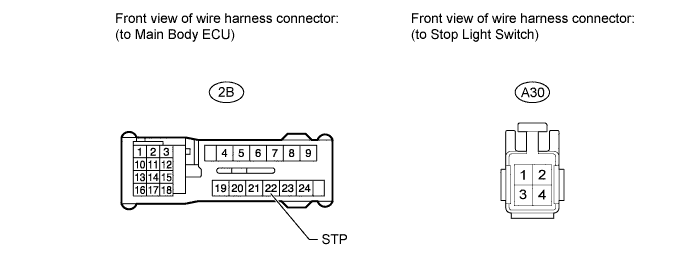
CHECK HARNESS AND CONNECTOR (STOP LIGHT SWITCH - MAIN BODY ECU AND BATTERY)
-
Disconnect the 2B main body ECU connector.
-
Disconnect the A30 stop light switch connector.
-
Measure the voltage and resistance according to the value(s) in the table below.
Standard Voltage Tester Connection Condition Specified Condition A30-2 - Body ground Always 11 to 14 V Standard Resistance Tester Connection Condition Specified Condition 2B-22 (STP) - A30-1 Always Below 1 Ω 2B-22 (STP) or A30-1 - Body ground Always 10 kΩ or higher
NG
REPLACE SHIFT LOCK CONTROL ECU SUB-ASSEMBLY Click here
OK
REPLACE MAIN BODY ECU (COWL SIDE JUNCTION BLOCK LH)
-
-
REPLACE STEERING LOCK ECU (STEERING LOCK ACTUATOR ASSEMBLY)
-
Replace the steering lock actuator assembly (steering lock ECU) Click here.
-
Register the recognition code (ECU code).
-
Check that the engine starts.
OK Engine starts.
NG
REPLACE ID CODE BOX (IMMOBILISER CODE ECU)
OK
END
-
-
REPLACE CERTIFICATION ECU (SMART KEY ECU ASSEMBLY)
-
Replace the certification ECU (smart key ECU assembly).
-
Register the recognition code (ECU code).
-
Check that the engine starts.
OK Engine starts.
NG
REPLACE ID CODE BOX (IMMOBILISER CODE ECU)
OK
END
-