ENTRY AND START SYSTEM (for Start Function), Diagnostic DTC:B2281

| DTC Code | DTC Name |
|---|---|
| B2281 | "P" Signal Malfunction |
DESCRIPTION
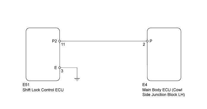
This DTC is stored when there is an abnormal circuit between the main body ECU and the shift lock control ECU.
| DTC Code | Detection Condition | Trouble Area |
|---|---|---|
| B2281 | Communication or the communication line between the main body ECU and shift lock control ECU is abnormal. |
|
WIRING DIAGRAM
INSPECTION PROCEDURE
PROCEDURE
-
READ VALUE USING INTELLIGENT TESTER (SHIFT P SIGNAL)
-
Use the Data List to check if the shift position signal is functioning properly.
Main Body Tester Display Measurement Item/Range Normal Condition Diagnostic Note Shift P Signal Shift P position signal/ON or OFF ON: Shift lever in P
OFF: Shift lever not in P
- Result Result Proceed to Display on the intelligent tester does not change according to shift lever operation A Display on the intelligent tester changes according to shift lever operation B
B 
REPLACE MAIN BODY ECU (COWL SIDE JUNCTION BLOCK LH)
A 
-
-
CHECK HARNESS AND CONNECTOR (SHIFT LOCK CONTROL ECU - MAIN BODY ECU AND BODY GROUND)
-
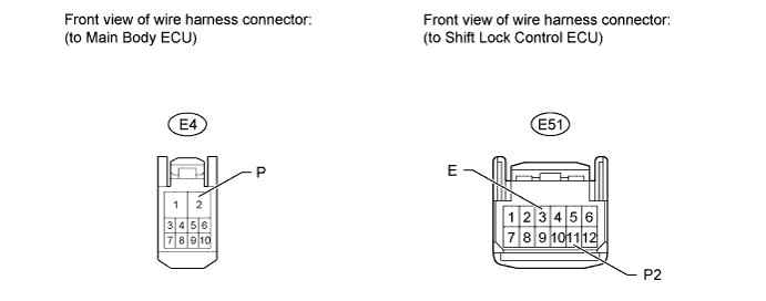
Disconnect the E4 main body ECU connector.
-
Disconnect the E51 shift lock control ECU connector.
-
Measure the resistance according to the value(s) in the table below.
Standard Resistance Tester Connection Condition Specified Condition E4-2 (P) - E51-11 (P2) Always Below 1 Ω E51-3 (E) - Body ground Always Below 1 Ω E4-2 (P) or E51-11 (P2) - Body ground Always 10 kΩ or higher
NG
REPAIR OR REPLACE HARNESS OR CONNECTOR
OK
-
-
INSPECT SHIFT LOCK CONTROL ECU SUB-ASSEMBLY
-
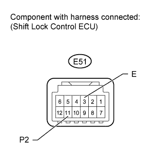
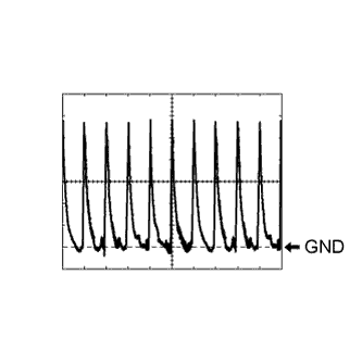
Check the signal waveform according to the condition(s) in the table below.
Reference Terminal No. (Symbol) Tool Setting Condition E51-11 (P2) - E51-3 (E) 2 V/DIV., 20 msec./DIV. Shift lever in P OK The waveform is similar to that shown in the illustration.
NG
REPLACE SHIFT LOCK CONTROL ECU SUB-ASSEMBLY Click here
OK 
REPLACE MAIN BODY ECU (COWL SIDE JUNCTION BLOCK LH)
-