ENTRY AND START SYSTEM (for Start Function) SYSTEM DESCRIPTION

-
PUSH-BUTTON START DESCRIPTION
-
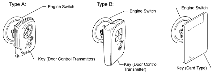
The push-button start uses a push-type engine switch, which the driver can operate by merely carrying the key. This system consists primarily of the main body ECU, engine switch, ID code box (immobiliser code ECU), steering lock ECU, key, ACC relay, IG1 No. 3 relay, integration relay (IG2 relay) and certification ECU (smart key ECU assembly). The main body ECU controls the system. This function operates in cooperation with the entry and start system. The table below shows the transition of the engine switch, which depends on whether the brake pedal is depressed or released.
-
This system has different power source mode patterns depending on the brake pedal and shift lever conditions.
Condition Power Source Mode Pattern Brake pedal not depressed, shift lever in P Each time engine switch is pushed
off → on (ACC) → on (IG) → off
Brake pedal not depressed When engine switch is pushed in engine started condition
Engine started → off
Brake pedal depressed, shift lever in P When engine switch is pushed once
off → engine start
Brake pedal depressed, shift lever in P When engine switch is pushed in on (ACC) condition
on (ACC) → engine start
Brake pedal depressed, shift lever in P When engine switch is pushed in on (IG) condition
on (IG) → engine start
Brake pedal depressed When engine switch is pushed in engine started condition
Engine started → off
When the battery of the key is low, the push-button start function can be operated by touching the key to the engine switch.
-
-
FUNCTION OF COMPONENT
Component Function Engine Switch
(Transponder Key Amplifier)
-
Transmits engine switch signal to main body ECU.
-
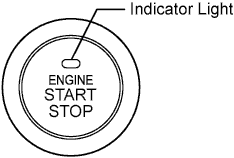
Informs driver of power source mode or system abnormality with indicator light illumination.
-
Receives ID code and transmits it to certification ECU (smart key ECU assembly) when key battery is depleted or transmitter is affected by wave noise, etc.
Key Receives signals from oscillators and returns ID code to entry door control receiver. Indoor Key Oscillator Receives request signal from certification ECU (smart key ECU assembly) and forms detection area in vehicle interior. Door Control Receiver Receives ID code from key and transmits it to certification ECU (smart key ECU assembly). Main Body ECU
-
Changes power source mode in 4 stages (off, on (ACC), on (IG), start) in accordance with state of park/neutral position switch.
-
Controls push-button start function in accordance with signals received from switches and each ECU.
Certification ECU (Smart Key ECU Assembly) Certifies ID code received from entry door control receiver and transmits certification results to ID code box (immobiliser code ECU) and steering lock ECU. Shift Lock Control ECU Outputs state of shift position to main body ECU. Stop Light Switch Outputs state of brake pedal to main body ECU. ID Code Box (Immobiliser Code ECU) Receives steering unlock or engine immobiliser unset signals from certification ECU (smart key ECU assembly), certifies them, and transmits each unset signal to steering lock ECU or ECM. ECM
-
Receives engine start request signal from main body ECU, turns on ST relay, and starts engine.
-
Receives signal from ID code box (immobiliser code ECU) and performs engine ignition and fuel injection.
-
-
SYSTEM FUNCTION
The electric controls of the push-button start function are described below:
Control Outline Engine Switch Control
-
When the driver operates the engine switch with a key in driver possession, the certification ECU (smart key ECU assembly) starts the indoor key oscillator, which transmits a request signal to the key. Upon receiving this signal, the key transmits an ID code signal to the door control receiver.
-
The ID code box (immobiliser code ECU) verifies the check results received from the certification ECU (smart key ECU assembly) via the LIN line and sends them to the main body ECU. Based on these results, the main body ECU authorizes operation of the engine switch.
Diagnosis When the main body ECU detects a malfunction, the main body ECU diagnoses and memorizes which section failed. -
-
CONSTRUCTION AND OPERATION
-
Engine switch:
The engine switch consists of a momentary type switch, 3 colored (amber, green, greenish white) LED, and the transponder key amplifier.
-
The greenish white LED is for illumination.
-
The amber and green LEDs are for the indicator light. The driver can check the present power source mode and whether the engine can start or not in accordance with the illumination state of the indicator light.
-
When the main body ECU detects an abnormality in the entry and start system, it makes the amber indicator light flash. If the engine is stopped in this state, it might not be possible to restart it.
-
-
Indicator light condition:
Engine Switch Indicator Light Condition Power Source Mode/Condition Indicator Light Condition Brake Pedal Released Brake Pedal Depressed, Shift Lever in P Off Off Illuminates (green) On (ACC), on (IG) Illuminates (amber) Illuminates (green) Engine running Off Off Steering lock not unlocked Flashes (green) for 30 seconds Flashes (green) for 30 seconds System malfunction Flashes (amber) for 15 seconds Flashes (amber) for 15 seconds Stop light switch malfunction with shift lever in P Flashes (green) for 15 seconds Flashes (green) for 15 seconds -
Main body ECU:
The main body ECU consists of the IG1 No. 3 relay and ACC relay actuation circuits and CPU.
-
-
SYSTEM NOT OPERATING NORMALLY (DUE TO KEY BATTERY DEPLETION, ELECTRICAL NOISE, ETC.)
-
To operate the push-button start function when the key battery is depleted or the transmitter is affected by wave noise, etc., touch the LEXUS mark of the key or card key to the engine switch while depressing the brake pedal with the shift lever in P.
-
The main body ECU transmits a key verification request signal from the stop light switch to the certification ECU (smart key ECU assembly).
-
The certification ECU (smart key ECU assembly) does not receive an ID code response from the door control receiver, so it activates the transponder key amplifier built into the engine switch.
-
The transponder key amplifier outputs an engine immobiliser radio wave to the key.
-
The key receives the radio wave, and returns a radio wave response to the transponder key amplifier.
-
The transponder key amplifier combines the key ID codes with the radio wave response, and transmits it to the certification ECU (smart key ECU assembly).
-
The certification ECU (smart key ECU assembly) judges and verifies the ID code, and transmits a key verification OK signal to the main body ECU. The buzzer in the combination meter sounds at the same time.
-
After the buzzer sounds, with the shift lever in P, if the engine switch is pressed within 10 seconds with the brake pedal not depressed, the power source mode changes to on (ACC) or on (IG), as in the normal condition.
-
-
DIAGNOSIS
The main body ECU can detect malfunctions in the push-button start function when the power source mode is on (IG).
When the ECU detects a malfunction, the amber indicator light of the engine switch flashes to warn the driver. At the same time, the ECU stores the 5-digit DTC (Diagnostic Trouble Code) in memory.
-
The indicator light warning continues for 15 seconds even after the power source mode is changed to off.
-
The DTC can be output by connecting the intelligent tester to the DLC3.
-
The push-button start function cannot be operated if a malfunction occurs.
-