ENTRY AND START SYSTEM (for Entry Function) Room Oscillator does not Recognize Key
DESCRIPTION
If the room oscillator does not recognize the key, one of the following may be the cause: 1) communication between the indoor electrical key antenna (for Front Floor) and electrical key transmitter cannot be performed; or 2) communication between the indoor electrical key antenna (for Rear Floor) and electrical key transmitter cannot be performed; or 3) communication between the indoor electrical key antenna (for Luggage Compartment) and electrical key transmitter cannot be performed.
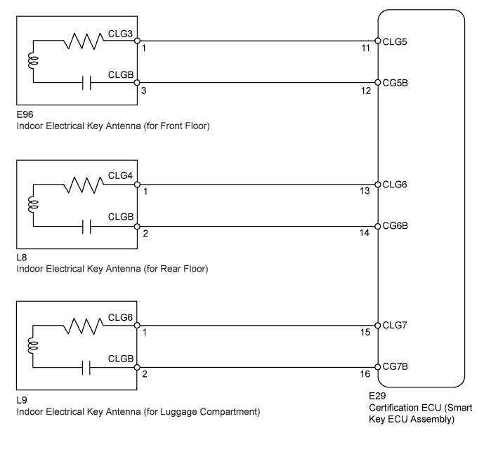
WIRING DIAGRAM
INSPECTION PROCEDURE
Note
-
Before performing the inspection, check that there are no problems related to the "CAN Communication System" and "LIN Communication System".
-
When using the intelligent tester with the engine switch off to troubleshoot: Connect the intelligent tester to the vehicle, and turn a courtesy light switch on and off at 1.5 second intervals until communication between the tester and vehicle begins.
PROCEDURE
-
CHECK ENTRY AND START SYSTEM (ENTRY FUNCTION)
-
Check that the entry lock and unlock function can be operated at each door Click here.
NG 
Go to DTC OF OTHER COMPONENTS (PROCEED TO PROBLEM SYMPTOM FLOWCHART FOR EACH DOOR) Click here
OK 
-
-
CHECK ENTRY AND START SYSTEM (START FUNCTION)
-
Remove the battery of the electrical key transmitter Click here.
-
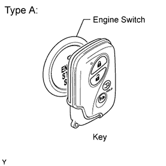
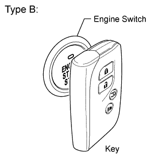
With the brake pedal depressed, touch the LEXUS mark of the key to the engine switch.
-
When operating the engine switch, check whether the power source mode changes.
OK Power source mode changes. Tech Tips
-
When the electrical key transmitter cannot be verified even though it is in the operating range of the start function, the engine start check can be performed by removing the transmitter battery from the electrical key transmitter and holding the transmitter against the engine switch.
-
When performing the check, if the power source mode changes, there is a problem with key certification inside the cabin.
-
NG
Go to ENTRY AND START SYSTEM (Power Source Mode does not Change) Click here
OK
-
-
CHECK WAVE ENVIRONMENT
-
Install the battery to the electrical key transmitter Click here.
-
Bring the electrical key transmitter near the indoor electrical key antenna (in center console), and perform an engine control system start check.
Note
If the key is brought within 0.2 m (0.656 ft.) of the center console, communication is not possible.
OK Engine starts. -
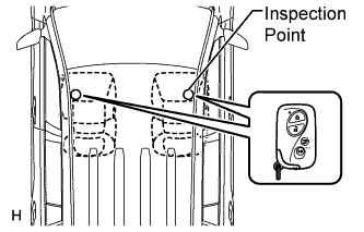
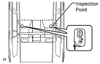
Bring the electrical key transmitter near the indoor electrical key antenna (in rear No. 1 seat cushion), and perform an engine control system start check.
Note
If the key is brought within 0.2 m (0.656 ft.) of the rear No. 1 seat cushion, communication is not possible.
OK Engine starts. -
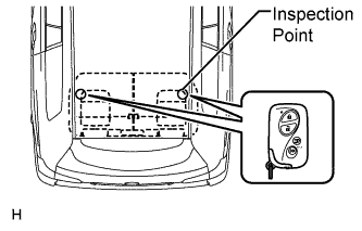
Bring the electrical key transmitter near the indoor electrical key antenna (in rear No. 2 seat cushion), and perform an engine control system start check.
Note
If the key is brought within 0.2 m (0.656 ft.) of the rear No. 2 seat cushion, communication is not possible.
Tech Tips
-
When the electrical key transmitter is brought near the indoor electrical key antenna, the possibility of wave interference decreases, and it can be determined if wave interference is causing the problem symptom.
-
If the inspection result is that the operation check is normal, the possibility of wave interference is high. Also, added vehicle components may cause wave interference, If installed, remove them and perform the operation check.
OK Engine starts. -
NG 
PERFORM KEY DIAGNOSTIC MODE INSPECTION Click here
OK 
AFFECTED BY WAVE INTERFERENCE
-
-
PERFORM KEY DIAGNOSTIC MODE INSPECTION
-
Diagnostic mode inspection (indoor electrical key antenna (for Front Floor)).
-
Connect the intelligent tester to the DLC3.
-
Turn the engine switch on (IG).
-
Turn the intelligent tester on.
-
Enter the following menus: Body / Entry&Start / Key Communication Check / Overhead + Front Room.
-
When the electrical key transmitter is placed on the driver seat or front passenger seat cushion, check that the wireless door lock buzzer sounds.
-
-
Diagnostic mode inspection (indoor electrical key antenna (for Rear Floor)).
-
Connect the intelligent tester to the DLC3.
-
Turn the engine switch on (IG).
-
Turn the intelligent tester on.
-
Enter the following menus: Body / Entry&Start / Key Communication Check / Overhead + Rear Room.
-
When the electrical key transmitter is placed on the rear seat cushion, check that the wireless door lock buzzer sounds.
-
-
Diagnostic mode inspection (indoor electrical key antenna (for Luggage Compartment)).
-
Connect the intelligent tester to the DLC3.
-
Turn the engine switch on (IG).
-
Turn the intelligent tester on.
-
Enter the following menus: Body / Entry&Start / Key Communication Check / Overhead + Back Door (inside) Room.
-
When the electrical key transmitter is placed on the rear seat cushion, check that the wireless door lock buzzer sounds.
Tech Tips
-
If the buzzer sounds, it can be determined that the vehicle interior transmitters are operating normally.
-
It is possible to check which indoor electrical key antenna (front floor, rear floor and luggage compartment) is operating by sounding the buzzer.
-
If the buzzer does not sound for any indoor electrical key antennas, the certification ECU (smart key ECU assembly) circuit may have a malfunction.
Result Result Proceed to Front floor operation check fails A Rear floor operation check fails B Luggage compartment operation check fails C Front floor, rear floor and luggage compartment operation checks are normal or fail D -
B
CHECK HARNESS AND CONNECTOR (CERTIFICATION ECU [SMART KEY ECU ASSEMBLY] - INDOOR ELECTRICAL KEY ANTENNA) Click here
C
CHECK HARNESS AND CONNECTOR (CERTIFICATION ECU [SMART KEY ECU ASSEMBLY] - INDOOR ELECTRICAL KEY ANTENNA) Click here
D
REPLACE CERTIFICATION ECU (SMART KEY ECU ASSEMBLY)
A
-
-
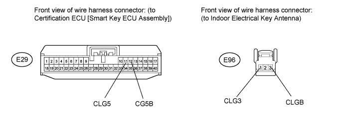
CHECK HARNESS AND CONNECTOR (CERTIFICATION ECU [SMART KEY ECU ASSEMBLY] - INDOOR ELECTRICAL KEY ANTENNA)
-
Disconnect the E29 ECU connector.
-
Disconnect the E96 antenna connector.
-
Measure the resistance according to the value(s) in the table below.
Standard Resistance Tester Connection Condition Specified Condition E96-1 (CLG3) - E29-11 (CLG5) Always Below 1 Ω E96-3 (CLGB) - E29-12 (CG5B) Always Below 1 Ω E96-1 (CLG3) - Body ground Always 10 kΩ or higher E96-3 (CLGB) - Body ground Always 10 kΩ or higher
NG
REPAIR OR REPLACE HARNESS OR CONNECTOR
OK
-
-
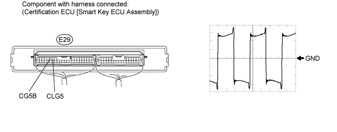
CHECK INDOOR ELECTRICAL KEY ANTENNA (for Front Floor)
-
Using an oscilloscope, check the waveform.
OK Tester Connection Tool Setting Switch Condition Specified Condition E29-11 (CLG5) - E29-12 (CG5B) 2 V/DIV., 2 μsec./DIV. (Reference) Engine switch on (IG) Waveform is as shown in the illustration
NG
REPLACE CERTIFICATION ECU (SMART KEY ECU ASSEMBLY)
OK
REPLACE INDOOR ELECTRICAL KEY ANTENNA (for Front Floor) Click here
-
-
CHECK HARNESS AND CONNECTOR (CERTIFICATION ECU [SMART KEY ECU ASSEMBLY] - INDOOR ELECTRICAL KEY ANTENNA)
-
Disconnect the E29 ECU connector.
-
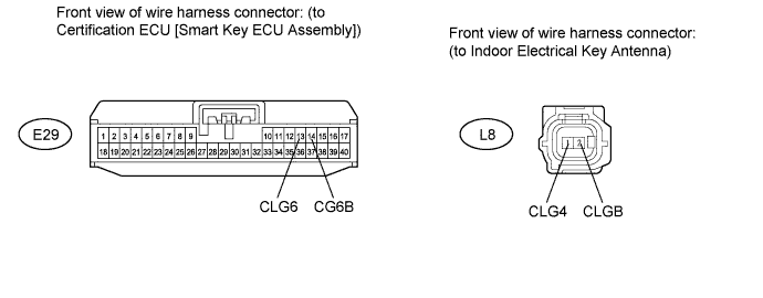
Disconnect the L8 antenna connector.
-
Measure the resistance according to the value(s) in the table below.
Standard Resistance Tester Connection Condition Specified Condition L8-1 (CLG4) - E29-13 (CLG6) Always Below 1 Ω L8-2 (CLGB) - E29-14 (CG6B) Always Below 1 Ω L8-1 (CLG4) - Body ground Always 10 kΩ or higher L8-2 (CLGB) - Body ground Always 10 kΩ or higher
NG
REPAIR OR REPLACE HARNESS OR CONNECTOR
OK
-
-
CHECK INDOOR ELECTRICAL KEY ANTENNA (for Rear Floor)
-
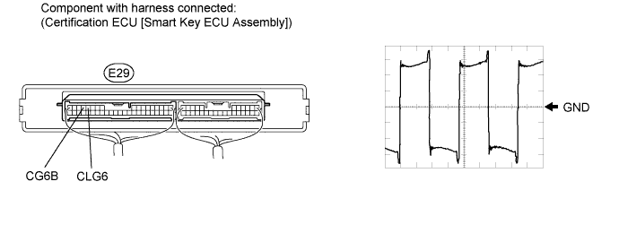
Using an oscilloscope, check the waveform.
OK Tester Connection Tool Setting Switch Condition Specified Condition E29-13 (CLG6) - E29-14 (CG6B) 2 V/DIV., 2 μsec./DIV. (Reference) Engine switch on (IG) Waveform is as shown in the illustration
NG
REPLACE CERTIFICATION ECU (SMART KEY ECU ASSEMBLY)
OK
REPLACE INDOOR ELECTRICAL KEY ANTENNA (for Rear Floor) Click here
-
-
CHECK HARNESS AND CONNECTOR (CERTIFICATION ECU [SMART KEY ECU ASSEMBLY] - INDOOR ELECTRICAL KEY ANTENNA)
-
Disconnect the E29 ECU connector.
-
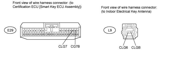
Disconnect the L9 antenna connector.
-
Measure the resistance according to the value(s) in the table below.
Standard Resistance Tester Connection Condition Specified Condition L9-1 (CLG6) - E29-15 (CLG7) Always Below 1 Ω L9-2 (CLGB) - E29-16 (CG7B) Always Below 1 Ω L9-1 (CLG6) - Body ground Always 10 kΩ or higher L9-2 (CLGB) - Body ground Always 10 kΩ or higher
NG
REPAIR OR REPLACE HARNESS OR CONNECTOR
OK
-
-
CHECK INDOOR ELECTRICAL KEY ANTENNA (for Luggage Compartment)
-
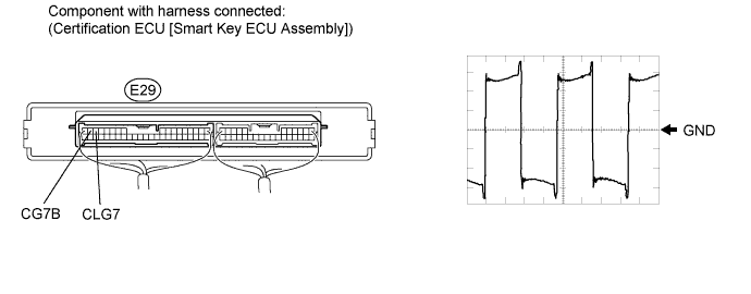
Using an oscilloscope, check the waveform.
OK Tester Connection Tool Setting Switch Condition Specified Condition E29-15 (CLG7) - E29-16 (CG7B) 2 V/DIV., 2 μsec./DIV. (Reference) Engine switch on (IG) Waveform is as shown in the illustration
NG
REPLACE CERTIFICATION ECU (SMART KEY ECU ASSEMBLY)
OK
REPLACE INDOOR ELECTRICAL KEY ANTENNA (for Luggage Compartment) Click here
-