ENTRY AND START SYSTEM (for Start Function), Diagnostic DTC:B2273

| DTC Code | DTC Name |
|---|---|
| B2273 | Ignition 2 Monitor Malfunction |
DESCRIPTION
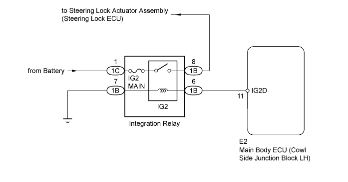
This DTC is stored when a malfunction occurs in the IG2D output circuit, which is between the integration relay (IG2 relay) actuation circuit inside the main body ECU and the integration relay (IG2 relay).
| DTC Code | Detection Condition | Trouble Area |
|---|---|---|
| B2273 | The integration relay (IG2 relay) actuation circuit inside the main body ECU or other related circuit is malfunctioning. |
|
WIRING DIAGRAM
INSPECTION PROCEDURE
PROCEDURE
-
READ VALUE USING INTELLIGENT TESTER (IG2 RELAY MONITOR [INSIDE])
-
Use the Data List to check if the integration relay (IG2 relay) is functioning properly.
Main Body Tester Display Measurement Item/Range Normal Condition Diagnostic Note IG2 Relay Monitor(Inside) Integration relay (IG2 relay) inner relay monitor/ON or OFF ON: Engine switch on (IG)
OFF: Engine switch off
- OK When the engine switch is turned on (IG), ON is displayed on the intelligent tester.
NG 
INSPECT FUSE (IG2 MAIN) Click here
OK 
-
-
CHECK WHETHER DTC OUTPUT RECURS
-
Clear the DTCs Click here.
-
Turn the engine switch on (IG), wait at least 10 seconds, and check whether DTC B2273 is output.
Result Result Proceed to No DTC output A DTC B2273 output B
B 
REPLACE MAIN BODY ECU (COWL SIDE JUNCTION BLOCK LH)
A 
USE SIMULATION METHOD TO CHECK Click here
-
-
INSPECT FUSE (IG2 MAIN)
-
Remove the IG2 MAIN fuse from the integration relay.
-
Measure the resistance according to the value(s) in the table below.
Standard Resistance Tester Connection Condition Specified Condition IG2 MAIN fuse Always Below 1 Ω
NG
REPLACE FUSE
OK
-
-
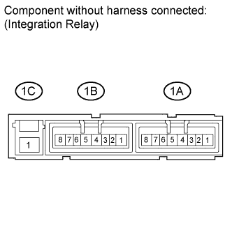
INSPECT INTEGRATION NO.1 RELAY (IG2 RELAY)
-
Install the IG2 MAIN fuse to the integration relay.
-
Remove the integration relay from the engine room relay block.
-
Measure the resistance according to the value(s) in the table below.
Standard Resistance Tester Connection Condition Specified Condition 1B-8 - 1C-1 Battery voltage applied to terminals 1B-6 and 1B-7 Below 1 Ω 1B-8 - 1C-1 Battery voltage not applied to terminals 1B-6 and 1B-7 10 kΩ or higher
NG
REPLACE INTEGRATION NO.1 RELAY
OK
-
-
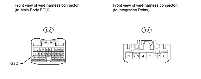
CHECK HARNESS AND CONNECTOR (INTEGRATION RELAY [IG2 RELAY] - MAIN BODY ECU AND BODY GROUND)
-
Disconnect the E2 main body ECU connector.
-
Disconnect the 1B integration relay connector.
-
Measure the resistance according to the value(s) in the table below.
Standard Resistance Tester Connection Condition Specified Condition E2-11 (IG2D) - 1B-6 Always Below 1 Ω 1B-7 - Body ground Always Below 1 Ω E2-11 (IG2D) or 1B-6 - Body ground Always 10 kΩ or higher
NG
REPAIR OR REPLACE HARNESS OR CONNECTOR
OK
REPLACE MAIN BODY ECU (COWL SIDE JUNCTION BLOCK LH)
-