DOOR CONTROL RECEIVER REMOVAL

-
REMOVE REAR NO. 2 SEAT ASSEMBLY RH
-
Remove the rear No. 2 seat assembly RH Click here.
-
-
REMOVE REAR STEP COVER
Tech Tips
Use the same procedure to remove the step cover on the other side.
-
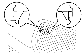
w/o Illumination Type Front Door Scuff Plate:
Detach the 2 claws and remove the step cover.
-
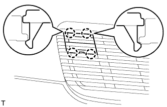
w/ Illumination Type Front Door Scuff Plate:
Detach the 4 claws and remove the step cover.
-
-
REMOVE REAR DOOR SCUFF PLATE RH
Tech Tips
Use the same procedures described for the LH side.
-
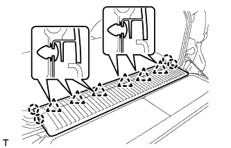
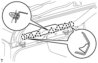
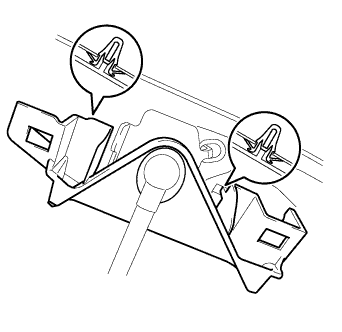
REMOVE REAR FLOOR MAT REAR SUPPORT PLATE
-
Detach the 6 clips and 4 claws, and remove the support plate.
-
-
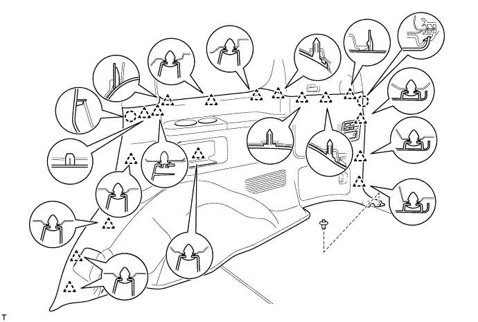
REMOVE FRONT QUARTER TRIM PANEL ASSEMBLY RH
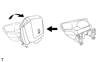
Tech Tips
When removing the front quarter trim panel, operate the reclining adjuster release handle and move the No. 1 rear seat to the position shown in the illustration.
-
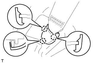
Detach the 3 claws and remove the cover.
-
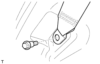
Remove the bolt and rear No. 1 seat belt anchor.
-
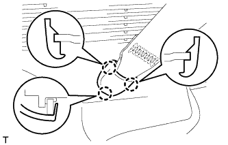
Detach the 3 claws and remove the cover.
-
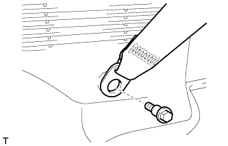
Remove the bolt and rear No. 2 seat belt anchor.
-
Remove the clip.
-
Detach the 17 clips and 2 claws.
-
Disconnect the thermistor connector and then remove the quarter trim panel.
-
-
REMOVE CENTER BACK DOOR GARNISH
-
Detach the 5 clips and 2 claws, and remove the back door garnish.
-
-
REMOVE BACK DOOR SIDE GARNISH RH
-
w/o Power Back Door:
Tech Tips
Use the same procedures described for the LH side.
-
w/ Power Back Door:
-
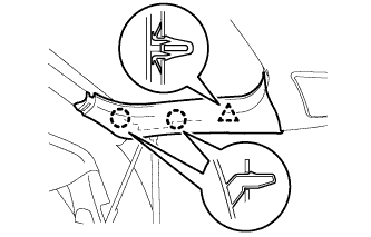
Detach the clip and 2 claws and remove the back door side garnish.
-
-
-
REMOVE BACK DOOR SERVICE HOLE COVER RH (w/ Power Back Door)
-
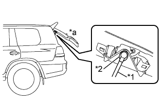
Text in Illustration *1 Power Back Door Rod *2 Hole of Back Door Service Hole Cover *a Back Door is Half-open Move the back door to a half-open position so that the hole in the center of the back door service hole cover is aligned lengthwise with the power back door rod.
-
Detach the 2 clips and separate the back door service hole cover, passing the power back door rod through the hole of the back door service hole cover.
Note
If the back door is in a fully-open position, the power back door rod will interfere with the hole of the back door service hole cover, so do not perform this operation with the back door in a fully open position.
Tech Tips
If any of the clips have remained on the back door, remove the clips from the back door and install them to the back door service hole cover.
-
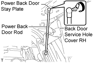
Remove the ball joint bolt, power back door rod and back door stay plate.
-
Remove the service hole cover from the power back door rod.
-
-
REMOVE REAR UPPER PILLAR GARNISH RH
-
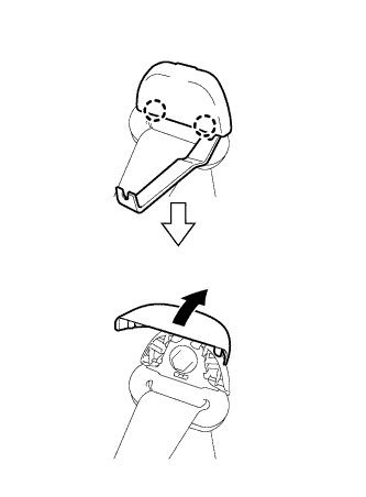
Using a moulding remover, detach the 2 claws and open the seat belt shoulder anchor cover.
-
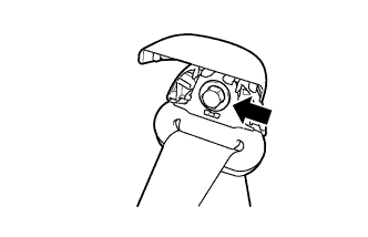
Remove the bolt and seat belt shoulder anchor.
-
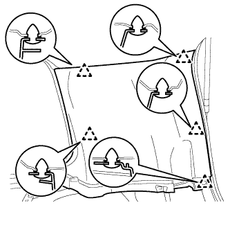
w/o Power Back Door:
-
Detach the 5 clips and remove the rear upper pillar garnish.
-
-
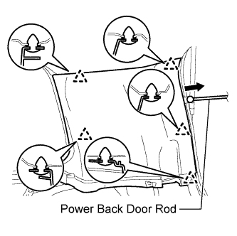
w/ Power Back Door:
-
Detach the 5 clips.
-
Pass the power back door rod through the rear upper pillar garnish, and remove the rear upper pillar garnish.
-
-
-
REMOVE DOOR CONTROL RECEIVER
-
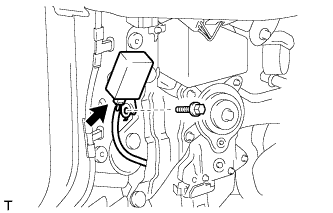
Disconnect the connector.
-
Remove the bolt and receiver.
-