DOOR CONTROL SWITCH INSPECTION

Tech Tips
-
Use the same procedures for LHD and RHD vehicles.
-
The procedures listed below are for LHD vehicles.
-
INSPECT DOOR CONTROL SWITCH ASSEMBLY
-

Measure the resistance according to the value(s) in the table below.
Standard Resistance Tester Connection Switch Condition Specified Condition 2 (L) - 3 (E) Lock Below 1 Ω 2 (L) - 3 (E)
4 (UL) - 3 (E)
Off 10 kΩ or higher 4 (UL) - 3 (E) Unlock Below 1 Ω
-
If the result is not as specified, replace the control switch assembly.
-
-
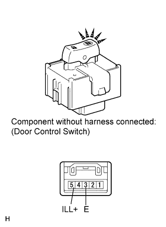
Apply battery voltage to the switch connector and check the indicator (LED) illumination condition.
OK Measurement Condition Specified Condition Battery positive (+) → Terminal 5 (ILL+) Indicator (LED) illuminates Battery negative (-) → Terminal 3 (E) If the result is not as specified, replace the door control switch assembly.
-