WIRELESS DOOR LOCK CONTROL SYSTEM TERMINALS OF ECU

-
CHECK MAIN BODY ECU (COWL SIDE JUNCTION BLOCK LH)
-
Disconnect the 2A, 2D and E3 ECU connectors.
-
Measure the resistance and voltage according to value(s) in the table below.
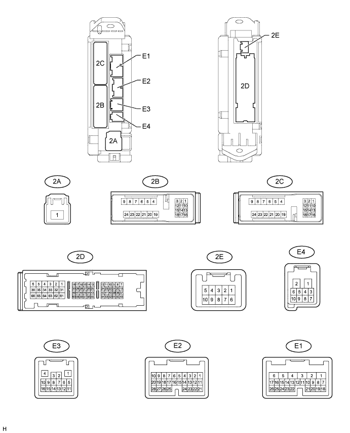
Terminal No. (Symbol) Wiring Color Terminal Description Condition Specified Condition 2D-62 (GND2) - Body ground W-B - Body ground Ground Always Below 1 Ω E3-1 (GND3) - Body ground BR - Body ground Ground Always Below 1 Ω E2-1(AM2) - 2D-62 (GND2) W - W-B Battery power supply Always 11 to 14 V E1-6(AM1) - 2D-62 (GND2) W - W-B Battery power supply Always 11 to 14 V 2A-1 (IG) - 2D-62 (GND2) B - W-B IG power supply Engine switch on (IG) 11 to 14 V
-
If the result is not as specified, there may be a malfunction on the wire harness side.
-
-
Reconnect the 2A, 2D and E3 ECU connectors.
-
Measure the voltage according to the value(s) in the table below.
Terminal No. (Symbol) Wiring Color Terminal Description Condition Specified Condition E1-24 (DCTY) - Body ground LHD: L - Body ground
RHD: P - Body ground
Driver side door courtesy light switch input Driver side door open Below 1 Ω Engine switch off and driver side door courtesy switch off Pulse generation (refer to waveform 1 and 2) E2-21 (PCTY) - Body ground LHD: P - Body ground
RHD: L - Body ground
Passenger side door courtesy light switch input Passenger side door open Below 1 Ω Engine switch off and passenger side door courtesy switch off Pulse generation (refer to waveform 3 and 4) 2C-2 (LCTY) - Body ground W - Body ground Rear side door LH courtesy light switch input Rear side door LH open Below 1 Ω Engine switch off and rear side door LH courtesy switch off Pulse generation (refer to waveform 5 and 6) E2-7 (RCTY) - Body ground G - Body ground Rear side door RH courtesy light switch input Rear side door RH open Below 1 Ω Engine switch off and rear side door RH courtesy switch off Pulse generation (refer to waveform 7 and 8) E2-25 (BCTY) - Body ground W - Body ground Back door courtesy light switch input Back door open Below 1 Ω Engine switch off and back door courtesy switch off Pulse generation (refer to waveform 9 and 10) E3-4 (HAZ) - Body ground BE - Body ground Turn signal light drive Hazard warning signal switch on Pulse generation Hazard warning signal switch off Below 1 V 2B-16 (DRL) - 2D-62 (GND2)* LG - W-B Headlight low drive Headlight dimmer switch low 11 to 14 V 2B-18 (HRLY) - 2D-62 (GND2)* L - W-B Headlight (high) drive Headlight dimmer switch high 11 to 14 V 2B-8 (TRLY) - 2D-62 (GND2)* G - W-B Taillight drive Headlight dimmer switch tail 11 to 14 V *: w/ Panic Switch
If the result is not as specified, the ECU may have a malfunction.
-
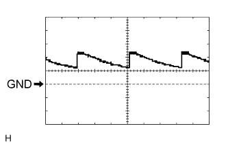
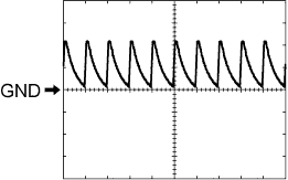
Using an oscilloscope, check waveform 1.
Waveform 1 (Reference) Item Content Terminal No. (Symbol) E1-24 (DCTY) - Body ground Tool Setting 5 V/DIV., 20 ms/DIV. Condition Engine switch off and driver side door courtesy switch off -
Using an oscilloscope, check waveform 2.
Waveform 2 (Reference) Item Content Terminal No. (Symbol) E1-24 (DCTY) - Body ground Tool Setting 5 V/DIV., 20 ms/DIV. Condition Engine switch off and driver side door courtesy switch off -
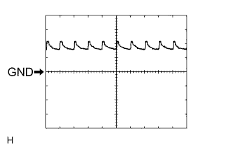
Using an oscilloscope, check waveform 3.
Waveform 3 (Reference) Item Content Terminal No. (Symbol) E2-21 (PCTY) - Body ground Tool Setting 5 V/DIV., 20 ms/DIV. Condition Engine switch off and passenger side door courtesy switch off -
Using an oscilloscope, check waveform 4.
Waveform 4 (Reference) Item Content Terminal No. (Symbol) E2-21 (PCTY) - Body ground Tool Setting 5 V/DIV., 20 ms/DIV. Condition Engine switch off and passenger side door courtesy switch off -
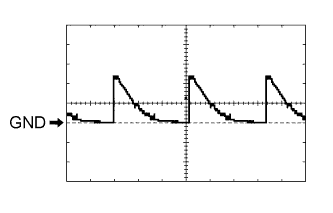
Using an oscilloscope, check waveform 5.
Waveform 5 (Reference) Item Content Terminal No. (Symbol) 2C-2 (LCTY) - Body ground Tool Setting 5 V/DIV., 20 ms/DIV. Condition Engine switch off and rear LH side door courtesy switch off -
Using an oscilloscope, check waveform 6.
Waveform 6 (Reference) Item Content Terminal No. (Symbol) 2C-2 (LCTY) - Body ground Tool Setting 5 V/DIV., 20 ms/DIV. Condition Engine switch off and rear LH side door courtesy switch off -
Using an oscilloscope, check waveform 7.
Waveform 7 (Reference) Item Content Terminal No. (Symbol) E2-7 (RCTY) - Body ground Tool Setting 5 V/DIV., 20 ms/DIV. Condition Engine switch off and rear RH side door courtesy switch off -
Using an oscilloscope, check waveform 8.
Waveform 8 (Reference) Item Content Terminal No. (Symbol) E2-7 (RCTY) - Body ground Tool Setting 5 V/DIV., 20 ms/DIV. Condition Engine switch off and rear RH side door courtesy switch off -
Using an oscilloscope, check waveform 9.
Waveform 9 (Reference) Item Content Terminal No. (Symbol) E2-25 (BCTY) - Body ground Tool Setting 5 V/DIV., 20 ms/DIV. Condition Engine switch off and back door closed -
Using an oscilloscope, check waveform 10.
Waveform 10 (Reference) Item Content Terminal No. (Symbol) E2-25 (BCTY) - Body ground Tool Setting 5 V/DIV., 20 ms/DIV. Condition Engine switch off and back door closed
-
-
CHECK CERTIFICATION ECU (SMART KEY ECU ASSEMBLY)
-
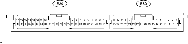
Disconnect the E29 and E30 ECU connectors.
-
Measure the resistance and voltage according to the value(s) in the table below.
Terminal No. (Symbol) Wiring Color Terminal Description Condition Specified Condition E29-17 (E) - Body ground W-B - Body ground Ground Always Below 1 Ω E29-1 (+B) - E29-17 (E) B - W-B Battery power supply Always 11 to 14 V E29-18 (IG) - E29-17 (E) B - W-B IG power supply Engine switch on (IG) 11 to 14 V Engine switch off Below 1 V
-
If the result is not as specified, there may be a malfunction on the wire harness side.
-
-
Reconnect the E29 and E30 ECU connectors.
-
Measure the voltage according to the value(s) in the table below.
Terminal No. (Symbol) Wiring Color Terminal Description Condition Specified Condition E29-39 (RSSI) - E29-17 (E) L - W-B Door control receiver electric wave existence signal Engine switch off, all doors closed and transmitter switch not pressed → pressed 11 to 14 V → Below 1 V E29-38 (RDA) - E29-17 (E) LG - W-B Door control receiver data input signal Engine switch off, all doors closed and transmitter switch not pressed → pressed Below 1 V → 11 to 14 V → Below 1 V E29-29 (RCO) - E29-17 (E) B - W-B Door control receiver power source Engine switch off, all doors closed and transmitter switch not pressed → pressed Below 1 V → 4.6 to 5.4 V → Below 1 V E29-21 (BZR) - Body ground* LG - Body ground Wireless door lock buzzer output Wireless door lock buzzer ON 11 to 14 V E29-21 (BZR) - Body ground* LG - Body ground Wireless door lock buzzer output Wireless door lock buzzer OFF Below 1 V Tech Tips
*: Except Europe and China
-
If the result is not as specified, the ECU may have a malfunction.
-
-
-
CHECK DOOR CONTROL RECEIVER

-
Disconnect the L21 receiver connector.
-
Measure the resistance and voltage according to the value(s) in the table below.
Terminal No. (Symbol) Wiring Color Terminal Description Condition Specified Condition L21-1 (GND) - Body ground W-B - Body ground Ground Always Below 1 Ω L21-4 (+5) - Body ground B - Body ground Battery power supply Always 4.6 to 5.4 V
-
If the result is not as specified, there may be a malfunction on the wire harness side.
-
-
-
CHECK POWER BACK DOOR UNIT (w/ Power Back Door System)
-
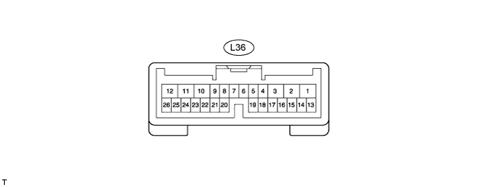
Disconnect the L36 unit connector.
-
Measure the voltage and resistance according to the value(s) in the table below.
Terminal No. (Symbol) Wiring Color Terminal Description Condition Specified Condition L36-11 (GND) - Body ground W-B - Body ground Ground Always Below 1 Ω L36-10 (ECUB) - Body ground R - Body ground Battery power supply Always 11 to 14 V If the result is not as specified, there may be a malfunction on the wire harness side.
-
Reconnect the L36 unit connector.
-
Measure the voltage according to the value(s) in the table below.
Terminal No. (Symbol) Wiring Color Terminal Description Condition Specified Condition L36-26 (BZR+) - Body ground L - Body ground Power back door warning buzzer signal Back door warning buzzer is sounding 11 to 14 V
Pulse generation
L36-26 (BZR+) - Body ground L - Body ground Power back door warning buzzer signal Back door warning buzzer is stopped Below 1 V If the result is not as specified, the ECU may have a malfunction.
-