POWER DOOR LOCK CONTROL SYSTEM TERMINALS OF ECU

-
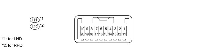
CHECK MULTIPLEX NETWORK MASTER SWITCH ASSEMBLY
-
Disconnect the I11*1 or I22*2 switch connector.
-
Measure the voltage and resistance according to the value(s) in the table below.
Terminal No. (Symbol) Wiring Color Terminal Description Condition Specified Condition I11-12 (GND) - Body ground*1 W-B - Body ground Ground Always Below 1 Ω I11-11 (B) - I11-12 (GND)*1 L - W-B Battery power supply Always 11 to 14 V I22-12 (GND) - Body ground*2 W-B - Body ground Ground Always Below 1 Ω I22-11 (B) - I22-12 (GND)*2 L - W-B Battery power supply Always 11 to 14 V *1: for LHD
*2: for RHD
If the result is not as specified, there may be a malfunction on the wire harness side.
-
-
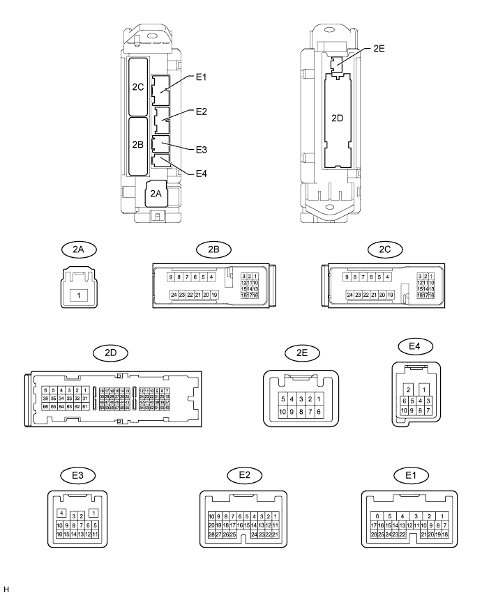
CHECK MAIN BODY ECU (COWL SIDE JUNCTION BLOCK LH)
-
Disconnect the 2A, 2B, 2D and E3 ECU connectors.
-
Measure the voltage and resistance according to the value(s) in the table below.
Terminal No. (Symbol) Wiring Color Terminal Description Condition Specified Condition 2B-20 (BATB) - Body ground L - Body ground Battery power supply Always 11 to 14 V 2A-1 (ALTB) - Body ground B - Body ground Power supply Engine switch on (ACC) 11 to 14 V 2A-1 (ALTB) - Body ground B - Body ground Power supply Engine switch off 11 to 14 V 2D-62 (GND2) - Body ground W-B - Body ground Ground Always Below 1 Ω E3-1 (GND3) - Body ground BR - Body ground Ground Always Below 1 Ω If the result is not as specified, there may be a malfunction on the wire harness side.
-
Reconnect the 2A, 2B, 2D and E3 ECU connectors.
-
Measure the voltage according to the value(s) in the table below.
Terminal No. (Symbol) Wiring Color Terminal Description Condition Specified Condition E1-24 (DCTY) - Body ground L*1 - Body ground
P*2 - Body ground
Driver side door courtesy light switch input Driver side door open Below 1 V E1-24 (DCTY) - Body ground L*1 - Body ground
P*2 - Body ground
Driver side door courtesy light switch input Engine switch off and driver side door courtesy light switch off Pulse generation
(see waveform 1 or 2)
E2-21 (PCTY) - Body ground P*1 - Body ground
L*2 - Body ground
Front passenger side door courtesy light switch input Front passenger side door open Below 1 V E2-21 (PCTY) - Body ground P*1 - Body ground
L*2 - Body ground
Front passenger side door courtesy light switch input Engine switch off and passenger side door courtesy light switch off Pulse generation
(see waveform 3 or 4)
2C-2 (LCTY) - Body ground W - Body ground Rear door LH courtesy light switch input Rear door LH open Below 1 V 2C-2 (LCTY) - Body ground W - Body ground Rear door LH courtesy light switch input Engine switch off and rear LH side door courtesy light switch off Pulse generation
(see waveform 5 or 6)
E2-7 (RCTY) - Body ground G - Body ground Rear door RH courtesy light switch input Rear door RH open Below 1 V E2-7 (RCTY) - Body ground G - Body ground Rear door RH courtesy light switch input Engine switch off and rear RH side door courtesy light switch off Pulse generation
(see waveform 7 or 8)
E2-25 (BCTY) - Body ground W - Body ground Back door courtesy light switch input Back door open Below 1 V E2-25 (BCTY) - Body ground W - Body ground Back door courtesy light switch input Engine switch off and back door closed Pulse generation
(see waveform 9 or 10)
2D-3 (ACT+) - Body ground L - Body ground Door lock motor lock drive output Master switch (door control switch) or driver side door key cylinder neutral position Below 1 V 2D-3 (ACT+) - Body ground L - Body ground Door lock motor lock drive output Master switch (door control switch) or driver side door key cylinder lock 11 to 14 V 2C-24 (ACT+) - Body ground L - Body ground Door lock motor lock drive output Master switch (door control switch) or driver side door key cylinder neutral position Below 1 V 2C-24 (ACT+) - Body ground L - Body ground Door lock motor lock drive output Master switch (door control switch) or driver side door key cylinder lock 11 to 14 V E1-5 (ACTD) - Body ground B - Body ground Driver side door lock motor unlock drive output Master switch (door control switch) or driver side door key cylinder neutral position Below 1 V E1-5 (ACTD) - Body ground B - Body ground Driver side door lock motor unlock drive output Master switch (door control switch) or driver side door key cylinder unlock 11 to 14 V 2D-2 (ACT-) - Body ground B - Body ground Front passenger side, and rear door RH door lock motor unlock drive output Master switch (door control switch) or driver side door key cylinder neutral position Below 1 V 2D-2 (ACT-) - Body ground B - Body ground Front passenger side, and rear door RH door lock motor unlock drive output Master switch (door control switch) or driver side door key cylinder unlock 11 to 14 V 2C-23 (ACT-) - Body ground B - Body ground Rear door LH and RH door lock motor unlock drive output Master switch (door control switch) or driver side door key cylinder neutral position Below 1 V 2C-23 (ACT-) - Body ground B - Body ground Rear door LH and RH door lock motor unlock drive output Master switch (door control switch) or driver side door key cylinder unlock 11 to 14 V E1-10 (UL3) - Body ground Y*1 - Body ground
L*2 - Body ground
Driver side door lock key switch input Driver side door key cylinder unlock Below 1 V E1-10 (UL3) - Body ground Y*1 - Body ground
L*2 - Body ground
Driver side door lock key switch input Engine switch off, all doors closed and driver side door key cylinder neutral position Pulse generation
(see waveform 11 or 12)
2D-53 (L2) - Body ground LG - Body ground Driver side door lock key switch input Driver side door key cylinder lock Below 1 V 2D-53 (L2) - Body ground LG - Body ground Driver side door lock key switch input Engine switch off, all doors closed and driver side door key cylinder neutral position Pulse generation
(see waveform 13 or 14)
E1-1 (TR+) - Body ground L - Body ground Back door lock motor unlock drive output Master switch (door control switch) or driver side door key cylinder neutral position Below 1 V E1-1 (TR+) - Body ground L - Body ground Back door lock motor unlock drive output Master switch (door control switch) or driver side door key cylinder unlock 11 to 14 V E1-9 (LSWD) - Body ground BE - Body ground Driver side door lock position switch input Driver side door unlocked Below 1 V E1-9 (LSWD) - Body ground BE - Body ground Driver side door lock position switch input Engine switch off, all doors closed and driver side door locked Pulse generation
(see waveform 15 or 16)
E2-27 (LSWP) - Body ground Y*1 - Body ground
BE*2 - Body ground
Front passenger side door lock position switch input Front passenger side door unlocked Below 1 V E2-27 (LSWP) - Body ground Y*1 - Body ground
BE*2 - Body ground
Front passenger side door lock position switch input Engine switch off, all doors closed and passenger side door locked Pulse generation
(see waveform 17 or 18)
2C-1 (LSWL) - Body ground BE - Body ground Rear door LH lock position switch input Rear door LH unlocked Below 1 V 2C-1 (LSWL) - Body ground BE - Body ground Rear door LH lock position switch input Engine switch off, all doors closed and rear door LH locked Pulse generation
(see waveform 19 or 20)
E2-5 (LSWR) - Body ground BE - Body ground Rear door RH lock position switch input Rear door RH unlocked Below 1 V E2-5 (LSWR) - Body ground BE - Body ground Rear door RH lock position switch input Engine switch off, all doors closed and rear door RH locked Pulse generation
(see waveform 21 or 22)
E1-26 (BDSU) - Body ground L - Body ground Back door opener switch input Back door opener switch off Below 1 V E1-26 (BDSU) - Body ground L - Body ground Back door opener switch input Back door opener switch on Pulse generation (see waveform 23 or 24)
-
*1: for LHD
-
*2: for RHD
If the result is not as specified, the ECU may have a malfunction.
-
-
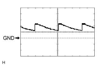
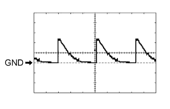
Using an oscilloscope, check waveform 1.
Waveform 1 (Reference) Item Content Terminal No. (Symbol) E1-24 (DCTY) - Body ground Tool Setting 5 V/DIV., 20 ms/DIV. Condition Engine switch off and driver side door courtesy light switch off -
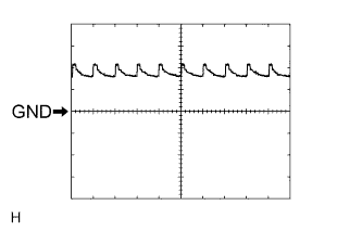
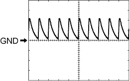
Using an oscilloscope, check waveform 2.
Waveform 2 (Reference) Item Content Terminal No. (Symbol) E1-24 (DCTY) - Body ground Tool Setting 5 V/DIV., 20 ms/DIV. Condition Engine switch off and driver side door courtesy light switch off -
Using an oscilloscope, check waveform 3.
Waveform 3 (Reference) Item Content Terminal No. (Symbol) E2-21 (PCTY) - Body ground Tool Setting 5 V/DIV., 20 ms/DIV. Condition Engine switch off and passenger side door courtesy light switch off -
Using an oscilloscope, check waveform 4.
Waveform 4 (Reference) Item Content Terminal No. (Symbol) E2-21 (PCTY) - Body ground Tool Setting 5 V/DIV., 20 ms/DIV. Condition Engine switch off and passenger side door courtesy light switch off -
Using an oscilloscope, check waveform 5.
Waveform 5 (Reference) Item Content Terminal No. (Symbol) 2C-2 (LCTY) - Body ground Tool Setting 5 V/DIV., 20 ms/DIV. Condition Engine switch off and rear LH side door courtesy light switch off -
Using an oscilloscope, check waveform 6.
Waveform 6 (Reference) Item Content Terminal No. (Symbol) 2C-2 (LCTY) - Body ground Tool Setting 5 V/DIV., 20 ms/DIV. Condition Engine switch off and rear LH side door courtesy light switch off -
Using an oscilloscope, check waveform 7.
Waveform 7 (Reference) Item Content Terminal No. (Symbol) E2-7 (RCTY) - Body ground Tool Setting 5 V/DIV., 20 ms/DIV. Condition Engine switch off and rear RH side door courtesy light switch off -
Using an oscilloscope, check waveform 8.
Waveform 8 (Reference) Item Content Terminal No. (Symbol) E2-7 (RCTY) - Body ground Tool Setting 5 V/DIV., 20 ms/DIV. Condition Engine switch off and rear RH side door courtesy light switch off -
Using an oscilloscope, check waveform 9.
Waveform 9 (Reference) Item Content Terminal No. (Symbol) E2-25 (BCTY) - Body ground Tool Setting 5 V/DIV., 20 ms/DIV. Condition Engine switch off and back door closed -
Using an oscilloscope, check waveform 10.
Waveform 10 (Reference) Item Content Terminal No. (Symbol) E2-25 (BCTY) - Body ground Tool Setting 5 V/DIV., 20 ms/DIV. Condition Engine switch off and back door closed -
Using an oscilloscope, check waveform 11.
Waveform 11 (Reference) Item Content Terminal No. (Symbol) E1-10 (UL3) - Body ground Tool Setting 5 V/DIV., 20 ms/DIV. Condition Engine switch off, all doors closed and driver side door key cylinder neutral position -
Using an oscilloscope, check waveform 12.
Waveform 12 (Reference) Item Content Terminal No. (Symbol) E1-10 (UL3) - Body ground Tool Setting 5 V/DIV., 20 ms/DIV. Condition Engine switch off, all doors closed and driver side door key cylinder neutral position -
Using an oscilloscope, check waveform 13.
Waveform 13 (Reference) Item Content Terminal No. (Symbol) 2D-53 (L2) - Body ground Tool Setting 5 V/DIV., 20 ms/DIV. Condition Engine switch off, all doors closed and driver side door key cylinder neutral position -
Using an oscilloscope, check waveform 14.
Waveform 14 (Reference) Item Content Terminal No. (Symbol) 2D-53 (L2) - Body ground Tool Setting 5 V/DIV., 20 ms/DIV. Condition Engine switch off, all doors closed and driver side door key cylinder neutral position -
Using an oscilloscope, check waveform 15.
Waveform 15 (Reference) Item Content Terminal No. (Symbol) E1-9 (LSWD) - Body ground Tool Setting 5 V/DIV., 20 ms/DIV. Condition Engine switch off, all doors closed and driver side door locked -
Using an oscilloscope, check waveform 16.
Waveform 16 (Reference) Item Content Terminal No. (Symbol) E1-9 (LSWD) - Body ground Tool Setting 5 V/DIV., 20 ms/DIV. Condition Engine switch off, all doors closed and driver side door locked -
Using an oscilloscope, check waveform 17.
Waveform 17 (Reference) Item Content Terminal No. (Symbol) E2-27 (LSWP) - Body ground Tool Setting 5 V/DIV., 20 ms/DIV. Condition Engine switch off, all doors closed and passenger side door locked -
Using an oscilloscope, check waveform 18.
Waveform 18 (Reference) Item Content Terminal No. (Symbol) E2-27 (LSWP) - Body ground Tool Setting 5 V/DIV., 20 ms/DIV. Condition Engine switch off, all doors closed and passenger side door locked -
Using an oscilloscope, check waveform 19.
Waveform 19 (Reference) Item Content Terminal No. (Symbol) 2C-1 (LSWL) - Body ground Tool Setting 5 V/DIV., 20 ms/DIV. Condition Engine switch off, all doors closed and rear door LH locked -
Using an oscilloscope, check waveform 20.
Waveform 20 (Reference) Item Content Terminal No. (Symbol) 2C-1 (LSWL) - Body ground Tool Setting 5 V/DIV., 20 ms/DIV. Condition Engine switch off, all doors closed and rear door LH locked -
Using an oscilloscope, check waveform 21.
Waveform 21 (Reference) Item Content Terminal No. (Symbol) E2-5 (LSWR) - Body ground Tool Setting 5 V/DIV., 20 ms/DIV. Condition Engine switch off, all doors closed and rear door RH locked -
Using an oscilloscope, check waveform 22.
Waveform 22 (Reference) Item Content Terminal No. (Symbol) E2-5 (LSWR) - Body ground Tool Setting 5 V/DIV., 20 ms/DIV. Condition Engine switch off, all doors closed and rear door RH locked -
Using an oscilloscope, check waveform 23.
Waveform 23 (Reference) Item Content Terminal No. (Symbol) E1-26 (BDSU) - Body ground Tool Setting 5 V/DIV., 20 ms/DIV. Condition Engine switch off, all doors closed and back door opener switch on -
Using an oscilloscope, check waveform 24.
Waveform 24 (Reference) Item Content Terminal No. (Symbol) E1-26 (BDSU) - Body ground Tool Setting 5 V/DIV., 20 ms/DIV. Condition Engine switch off, all doors closed and back door opener switch on
-