CAN COMMUNICATION SYSTEM (for RHD) SYSTEM DIAGRAM

Tech Tips
-
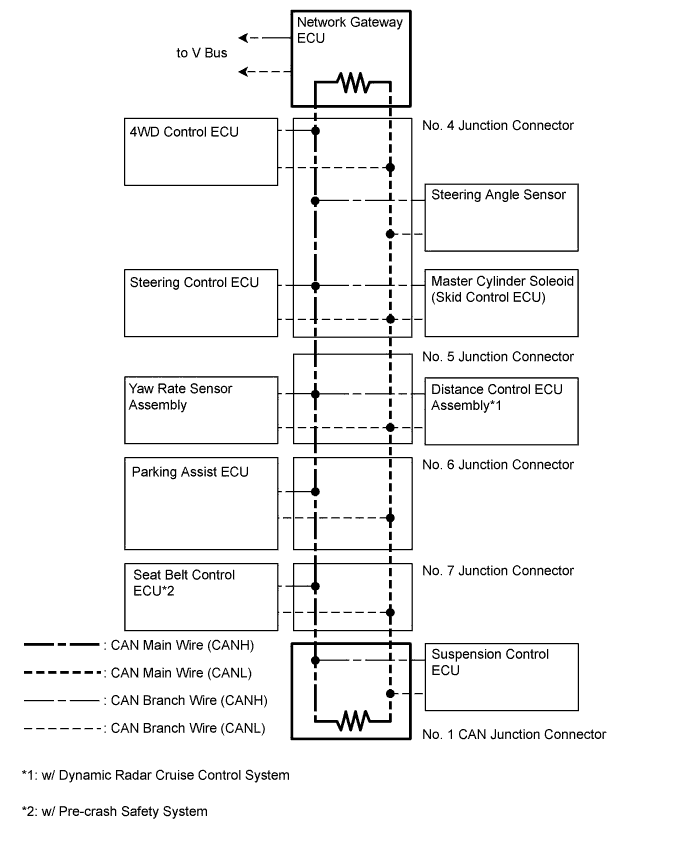
The master cylinder solenoid (skid control ECU) stores steering sensor and yaw rate sensor assembly DTCs and performs DTC communication by receiving information from the steering sensor and yaw rate sensor.
-
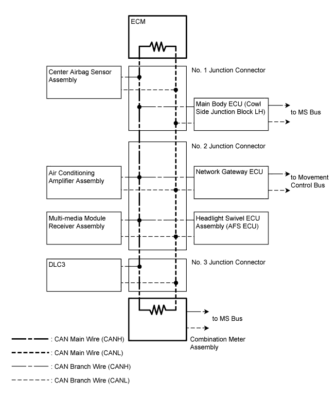
The ECM uses the CAN communication system to perform DTC communication instead of the conventional communication line (SIL).
-
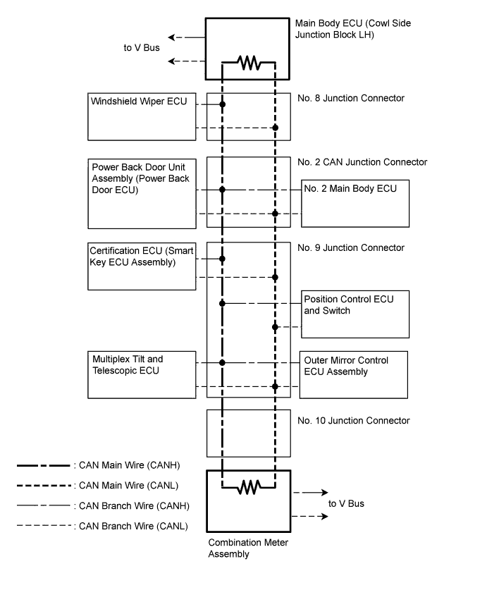
System Diagram
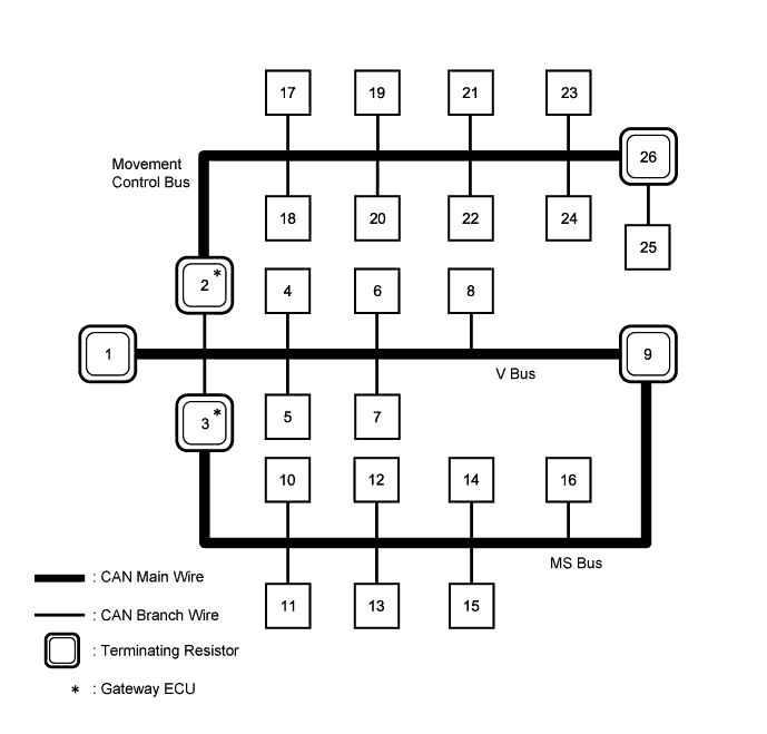
No. ECU/Sensor Name 1 ECM 2 Network gateway ECU 3 Main body ECU (cowl side junction block LH) 4 DLC3 5 Air conditioning amplifier assembly 6 Center airbag sensor assembly 7 Multi-media module receiver assembly 8 Headlight Swivel ECU assembly (AFS ECU) 9 Combination meter assembly 10 Certification ECU (smart key ECU assembly) 11 Multiplex tilt and telescopic ECU 12 Outer mirror control ECU assembly 13 Position control ECU and switch 14 No. 2 main body ECU 15 Power back door unit assembly (power back door ECU) 16 Windshield wiper ECU 17 Master cylinder solenoid (skid control ECU) 18 Yaw rate sensor assembly 19 Steering angle sensor 20 4WD control ECU 21 Parking assist ECU 22 Seat belt control ECU*1 23 Distance control ECU assembly*2 24 Steering control ECU 25 Suspension control ECU 26 No. 1 CAN junction connector
-
*1: w/ Pre-crash Safety System
-
*2: w/ Dynamic Radar Cruiser Control System
-
-
V Bus
-
Movement Control Bus
-
MS Bus