FRONT BUMPER REASSEMBLY

-
INSTALL FRONT BUMPER EXTENSION MOUNTING BRACKET
-
for Type A:
-
Attach the 4 claws to install the front bumper extension mounting bracket.
-
Install the 2 screws.
-
-
for Type B:
-
Attach the 2 claws to install the front bumper extension mounting bracket.
-
Install the 2 screws.
-
-
-
INSTALL FRONT BUMPER PROTECTOR
Tech Tips
When installing the front bumper protector, heat the front bumper surface using a heat light.
Standard Item Temperature Front Bumper 20 to 30°C (68 to 86°F) Note
Do not heat the front bumper excessively.
-
Clean the front bumper surface.
-
Using a heat light, heat the front bumper surface.
-
Remove the double-sided tape from the front bumper.
-
Wipe off any tape adhesive residue with cleaner.
-
-
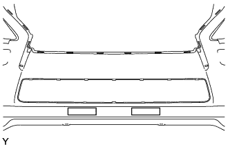
Install a new front bumper protector.
-
Remove the peeling paper from the face of 2 new front bumper protectors.
Tech Tips
After removing the peeling paper, keep the exposed adhesive free from foreign matter.
-
Install the 2 front bumper protectors as shown in the illustration.
-
-
-
INSTALL LOWER RADIATOR GRILLE
-
Attach the 14 claws to install the lower radiator grille.
-
-
INSTALL FRONT BUMPER HOLE COVER LH
-
Attach the 4 claws to install the front bumper hole cover LH.
-
-
INSTALL FRONT BUMPER HOLE COVER RH
Tech Tips
Use the same procedure described for the LH side.
-
INSTALL FRONT BUMPER GARNISH LH
-
Attach the 3 claws.
-
Install the 2 screws and the front bumper garnish LH.
-
-
INSTALL FRONT BUMPER GARNISH RH
Tech Tips
Use the same procedure described for the LH side.
-
INSTALL FOG LIGHT ASSEMBLY LH
-
Attach the 2 guides to install the fog light assembly LH.
-
Install the 2 screws.
- Torque:
- 1.8 N*m { 18 kgf*cm, 16 in.*lbf }
-
Connect the connector.
-
-
INSTALL FOG LIGHT ASSEMBLY RH
Tech Tips
Use the same procedure described for the LH side.
-
INSTALL FRONT BUMPER INNER BRACKET
-
Attach the 3 claws to install the front bumper inner bracket.
-
-
INSTALL NO. 2 ULTRASONIC SENSOR RETAINER
Tech Tips
Use the same procedure to install the No. 2 ultrasonic sensor retainer on the other side.
-
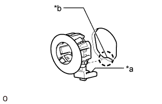
Text in Illustration *a Protrusion *b Keyhole Temporarily install the No. 2 ultrasonic sensor retainer to the front bumper.
Note
-
Do not damage the bumper with the protrusion when installing the retainer.
-
Securely install the No. 2 ultrasonic sensor retainer so that there are no gaps between the retainer and surface of the front bumper.
-
-
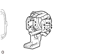
Attach the 2 claws to install the No. 2 ultra sonic sensor retainer.
-
-
INSTALL NO. 1 ULTRASONIC SENSOR
Tech Tips
Use the same procedure to install the No. 1 ultrasonic sensor on the other side.
-
Attach the 2 claws to install the ultrasonic sensor.
Note
Push the No. 2 ultrasonic sensor retainer from the outside of the bumper when there is a gap between the retainer and the bumper surface. In this case, do not push on the No. 1 ultrasonic sensor.
-
-
INSTALL ULTRASONIC SENSOR CLIP
-
Attach the 4 claws to install the ultrasonic sensor clip.
Note
Hold the No. 1 ultrasonic sensor in place so that the No. 2 ultrasonic sensor retainer does not come out when installing the ultrasonic sensor clip.
-
-
INSTALL NO. 4 ENGINE ROOM WIRE
-
Attach the 10 clamps to install the No. 4 engine room wire.
-
Connect the 4 connectors.
-
-
INSTALL HEADLIGHT WASHER ACTUATOR SUB-ASSEMBLY LH (w/ Headlight Cleaner System)
-
Attach the 2 claws.
-
Install the headlight washer actuator sub-assembly LH with the bolt.
- Torque:
- 1.1 N*m { 11 kgf*cm, 10 in.*lbf }
-
-
INSTALL HEADLIGHT WASHER ACTUATOR SUB-ASSEMBLY RH (w/ Headlight Cleaner System)
Tech Tips
Use the same procedure described for the LH side.
-
INSTALL TYPE 1 HEADLIGHT WASHER NOZZLE SUB-ASSEMBLY LH (w/ Headlight Cleaner System)
-
Attach the 2 claws to install the type 1 headlight washer nozzle sub-assembly LH.
-
-
INSTALL TYPE 1 HEADLIGHT WASHER NOZZLE SUB-ASSEMBLY RH (w/ Headlight Cleaner System)
Tech Tips
Use the same procedure described for the LH side.
-
INSTALL HEADLIGHT CLEANER HOSE (w/ Headlight Cleaner System)
-
Attach the 5 clamps and install the headlight cleaner hose.
-
Connect the headlight cleaner hose.
-