GENERATOR (for 150 A Type) INSTALLATION

-
INSTALL GENERATOR ASSEMBLY
-
Install the stud bolt.
- Torque:
- 10 N*m { 102 kgf*cm, 7 ft.*lbf }
-
Install the generator with the 3 bolts and nut.
- Torque:
- 43 N*m { 438 kgf*cm, 32 ft.*lbf }
-
Connect the harness bracket to the generator with the bolt.
- Torque:
- 31 N*m { 316 kgf*cm, 23 ft.*lbf }
-
Connect the generator wire with the nut.
- Torque:
- 9.8 N*m { 100 kgf*cm, 87 in.*lbf }
-
Close the terminal cap.
-
Connect the generator connector.
-
-
CONNECT OIL COOLER PIPE ASSEMBLY
-
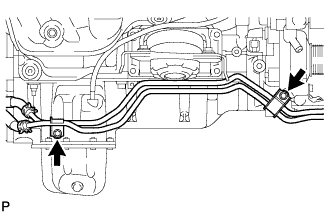
Connect the oil cooler pipe with the 2 bolts.
- Torque:
- 14 N*m { 143 kgf*cm, 10 ft.*lbf }
-
-
CONNECT VANE PUMP ASSEMBLY
Tech Tips
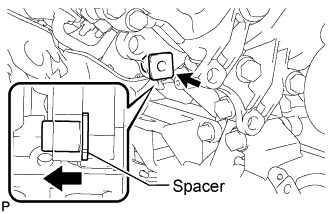
Before performing the following procedures, move the spacer until the vane pump can be installed.
-
Connect the vane pump to the timing chain cover with the 2 bolts.
- Torque:
- 21 N*m { 214 kgf*cm, 15 ft.*lbf }
-
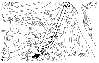
Connect the 2 clamps and power steering oil pressure switch connector.
-
-
INSTALL AIR CLEANER ASSEMBLY
-
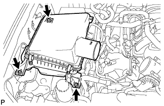
Install the air cleaner with the 3 bolts.
- Torque:
- 5.0 N*m { 51 kgf*cm, 44 in.*lbf }
-
-
INSTALL AIR CLEANER HOSE ASSEMBLY
-
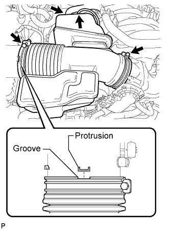
Install the air cleaner hose so that the protrusion of the air cleaner cap aligns with the groove of the hose as shown in the illustration.
-
Tighten the 2 clamps.
- Torque:
- 5.0 N*m { 51 kgf*cm, 44 in.*lbf }
-
Connect the vacuum hose.
-
Connect the No. 2 ventilation hose.
-
-
INSTALL FRONT FENDER APRON SEAL FRONT RH
-
Install the fender apron seal with the 3 clips.
-
-
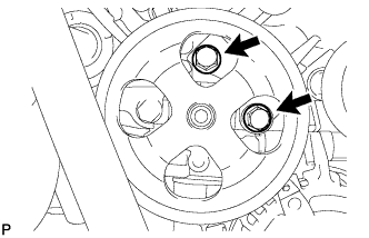
INSTALL FAN & GENERATOR V BELT
-
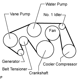
Set the V belt onto every part.
-
While turning the belt tensioner counterclockwise, remove the bar.
Note
Make sure that the V belt is properly set to each pulley.
-
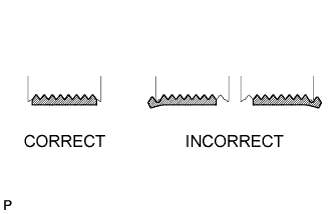
After installing the belt, check that it fits properly in the ribbed grooves.
Tech Tips
Make sure to check by hand that the belt has not slipped out of the grooves on the bottom of the pulley.
-
-
INSTALL NO. 1 ENGINE UNDER COVER SUB-ASSEMBLY
-
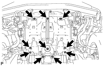
Install the No. 1 engine under cover with the 10 bolts.
- Torque:
- 29 N*m { 296 kgf*cm, 21 ft.*lbf }
-
-
INSTALL FRONT FENDER SPLASH SHIELD SUB-ASSEMBLY LH
-
Push in the clip to install the front fender splash shield sub-assembly LH.
-
Install the 3 bolts and 2 screws.
-
-
INSTALL FRONT FENDER SPLASH SHIELD SUB-ASSEMBLY RH
Tech Tips
Use the same procedure described for the LH side.
-
CONNECT CABLE TO NEGATIVE BATTERY TERMINAL
Note
When disconnecting the cable, some systems need to be initialized after the cable from the cable is reconnected Click here.
-
INSTALL V-BANK COVER SUB-ASSEMBLY
-
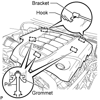
Attach the 2 V-bank cover hooks to the bracket. Then align the 3 V-bank cover grommets with the 3 pins, and press down on the V-bank cover to attach the pins.
-
-
INSTALL UPPER RADIATOR SUPPORT SEAL
-
Install the upper radiator support seal with the 3 clips.
-
-
INSTALL ENGINE ROOM SIDE COVER LH
-
Install the engine room side cover LH with the 7 clips.
-
-
INSTALL ENGINE ROOM SIDE COVER RH
-
Install the engine room side cover RH with the 7 clips.
-