GENERATOR (for 150 A Type) REMOVAL

-
REMOVE ENGINE ROOM SIDE COVER LH
-
Remove the 7 clips and engine room side cover LH.
-
-
REMOVE ENGINE ROOM SIDE COVER RH
-
Remove the 7 clips and engine room side cover RH.
-
-
REMOVE UPPER RADIATOR SUPPORT SEAL
-
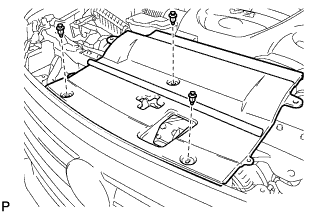
Remove the 3 clips and upper radiator support seal.
-
-
REMOVE V-BANK COVER SUB-ASSEMBLY
-
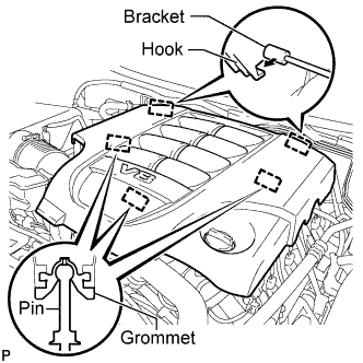
Raise the front of the V-bank cover to detach the 3 pins. Then remove the 2 V-bank cover hooks from the bracket, and remove the V-bank cover.
-
-
DISCONNECT CABLE FROM NEGATIVE BATTERY TERMINAL
Note
-
w/ Navigation System:
After the engine switch is turned off, the HDD navigation system requires approximately 6 minutes to record various types of memory and settings. As a result, after turning the engine switch off, wait 6 minutes or more before disconnecting the cable from the negative (-) battery terminal.
-
When disconnecting the cable, some systems need to be initialized after the cable is reconnected Click here.
-
-
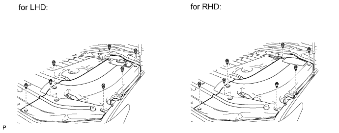
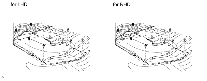
REMOVE FRONT FENDER SPLASH SHIELD SUB-ASSEMBLY LH
-
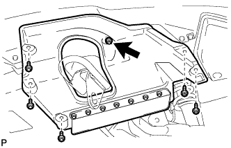
Remove the 3 bolts and 2 screws.
-
Turn the clip indicated by the arrow in the illustration to remove the front fender splash shield sub-assembly LH.
-
-
REMOVE FRONT FENDER SPLASH SHIELD SUB-ASSEMBLY RH
Tech Tips
Use the same procedure described for the LH side.
-
REMOVE NO. 1 ENGINE UNDER COVER SUB-ASSEMBLY
-
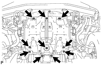
Remove the 10 bolts and No. 1 engine under cover.
-
-
REMOVE FAN & GENERATOR V BELT
-
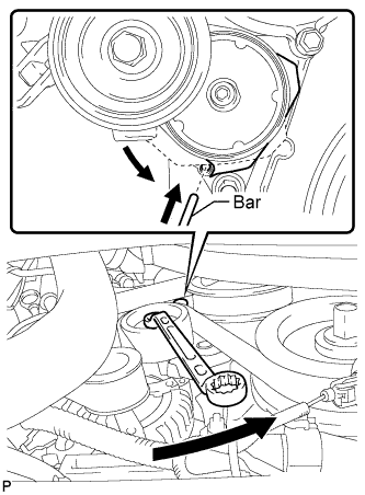
While turning the belt tensioner counterclockwise, align the service hole for the belt tensioner and the belt tensioner fixing position, and then insert a bar of φ5 mm (0.197 in.) into the service hole to fix the belt tensioner in place.
Tech Tips
The pulley bolt for the belt tensioner has a left-hand thread.
-
Remove the V belt.
-
-
REMOVE FRONT FENDER APRON SEAL FRONT RH
-
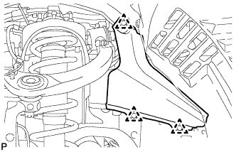
Using a clip remover, remove the 3 clips and fender apron seal.
-
-
REMOVE AIR CLEANER HOSE ASSEMBLY
-
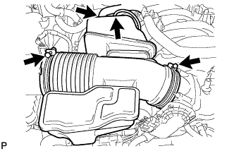
Disconnect the vacuum hose and No. 2 ventilation hose.
-
Loosen the 2 hose clamps.
-
Remove the air cleaner hose.
-
-
REMOVE AIR CLEANER ASSEMBLY
-
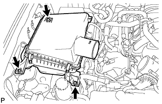
Remove the 3 bolts and air cleaner.
-
-
DISCONNECT VANE PUMP ASSEMBLY
-
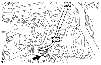
Disconnect the 2 clamps and power steering oil pressure switch connector.
-
Remove the 2 bolts and disconnect the vane pump.
-
-
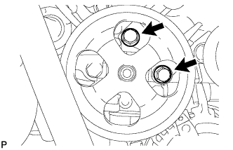
DISCONNECT OIL COOLER PIPE ASSEMBLY
-
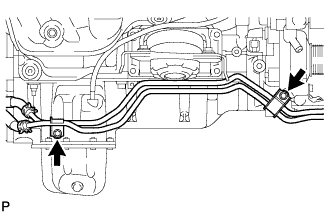
Remove the 2 bolts and disconnect the oil cooler pipe.
-
-
REMOVE GENERATOR ASSEMBLY
-
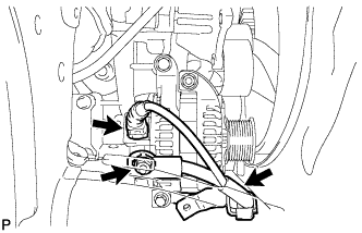
Disconnect the generator connector.
-
Open the terminal cap.
-
Remove the nut and disconnect the generator wire.
-
Remove the bolt and disconnect the wire harness bracket from the generator.
-
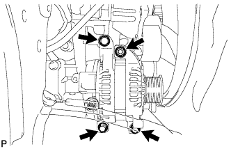
Remove the 3 bolts, nut and generator.
-
Remove the stud bolt.
-