G-BOOK SYSTEM Emergency Call Switch Indicator Circuit
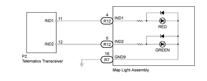
WIRING DIAGRAM
INSPECTION PROCEDURE
Tech Tips
When replacing the telematics transceiver, perform the vehicle contract setting Click here.
PROCEDURE
-
CHECK HARNESS AND CONNECTOR (TELEMATICS TRANSCEIVER - MAP LIGHT ASSEMBLY)
-
Disconnect the P2 telematics transceiver connector.
-
Disconnect the R7 and R12 map light assembly connectors.
-
Measure the resistance according to the value(s) in the table below.
Standard Resistance Tester Connection Condition Specified Condition P2-11 (IND1) - R12-4 (IND1) Always Below 1 Ω P2-12 (IND2) - R12-5 (IND2) Always Below 1 Ω R7-16 (GND9) - Body ground Always Below 1 Ω P2-11 (IND1) - Body ground Always 10 KΩ or higher P2-12 (IND2) - Body ground Always 10 KΩ or higher
NG 
REPAIR OR REPLACE HARNESS OR CONNECTOR
OK 
-
-
INSPECT MAP LIGHT ASSEMBLY
-
Disconnect the R7 AND R12 map light assembly connectors.
-
Connect 2 dry-cell batteries in series.
-
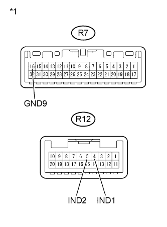
Text in Illustration *1 Component without harness connected
(Map Light Assembly)
Connect a positive (+) lead to terminal R12-4 (IND1) or R12-5 (IND2), and a negative (-) lead to terminal R7-16 (GND9) of the map light assembly connector.
-
Check if the illumination for the emergency call switch comes on.
OK The red indicator comes on when the positive (+) lead from the batteries is connected to terminal R12-4 (IND1) and the negative (-) lead is connected to terminal R7-16 (GND9). The green indicator comes on when the positive (+) lead from the batteries is connected to terminal R12-5 (IND2) and the negative (-) lead is connected to terminal R7-16 (GND9).
NG
REPLACE MAP LIGHT ASSEMBLY Click here
OK 
REPLACE TELEMATICS TRANSCEIVER Click here
-