G-BOOK SYSTEM Emergency Call Switch Illumination Circuit
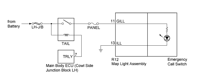
WIRING DIAGRAM
INSPECTION PROCEDURE
Tech Tips
When replacing the telematics transceiver, perform the vehicle contract setting Click here.
Note
Inspect the fuses for circuits related to this system before performing the following inspection procedure.
PROCEDURE
-
CHECK HARNESS AND CONNECTOR (TELEMATICS TRANSCEIVER - BATTERY AND BODY GROUND)
-
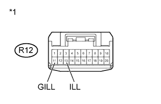
Text in Illustration *1 Front view of wire harness connector
(to Map Light Assembly)
Disconnect the R12 map light assembly connector.
-
Measure the resistance according to the value(s) in the table below.
Standard Resistance Tester Connection Condition Specified Condition R12-13 (ILL) - Body ground Always 10 kΩ or higher -
Measure the voltage according to the value(s) in the table below.
Standard Voltage Tester Connection Switch Condition Specified Condition R12-11 (GILL) - Body ground Light control switch in TAIL or HEAD 11 to 14 V
NG 
REPAIR OR REPLACE HARNESS OR CONNECTOR
OK 
REPLACE MAP LIGHT ASSEMBLY Click here
-