G-BOOK SYSTEM, Diagnostic DTC:B15C6

| DTC Code | DTC Name |
|---|---|
| B15C6 | Ignition Switch Signal Malfunction |
DESCRIPTION
If vehicle movement (10 km/h (6 mph) or more for 10 seconds) is detected based on the location data sent from the multi-media module receiver assembly even when the telematics transceiver detects that the engine switch is off, this DTC will be stored.
| DTC No. | DTC Detection Condition | Trouble Area |
|---|---|---|
| B15C6 | IG signal error |
|
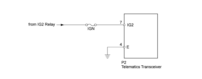
WIRING DIAGRAM
INSPECTION PROCEDURE
Note
Inspect the fuses and relays for circuits related to this system before performing the following inspection procedure.
Tech Tips
When replacing the telematics transceiver, perform the vehicle contract setting Click here.
PROCEDURE
-
CLEAR DTC
-
Clear the DTC Click here.
NEXT 
-
-
CHECK DTC
-
Recheck for DTCs and check if the same trouble occurs again Click here.
OK No DTC is output.
NG 
CHECK HARNESS AND CONNECTOR (TELEMATICS TRANSCEIVER - BATTERY AND BODY GROUND) Click here
OK 
USE SIMULATION METHOD TO CHECK Click here
-
-
CHECK HARNESS AND CONNECTOR (TELEMATICS TRANSCEIVER - BATTERY AND BODY GROUND)
-
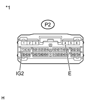
Text in Illustration *1 Front view of wire harness connector
(to Telematics Transceiver)
Disconnect the P2 telematics transceiver connector.
-
Measure the resistance according to the value(s) in the table below.
Standard Resistance Tester Connection Condition Specified Condition P2-4 (E) - Body ground Always Below 1 Ω -
Measure the voltage according to the value(s) in the table below.
Standard Voltage Tester Connection Switch Condition Specified Condition P2-7 (IG2) - Body ground Engine switch on (IG) 11 to 14 V
NG 
REPAIR OR REPLACE HARNESS OR CONNECTOR
OK
REPLACE TELEMATICS TRANSCEIVER Click here
-