INSTRUMENT PANEL SPEAKER INSTALLATION

Tech Tips
-
Use the same procedures for the LH side and RH side.
-
The procedures listed below are for the LH side.
-
A bolt without a torque specification is shown in the standard bolt chart Click here.
-
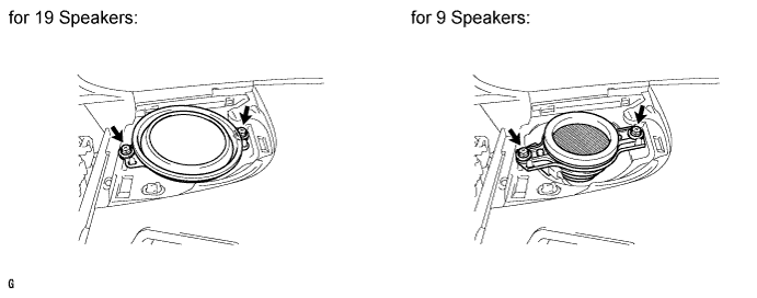
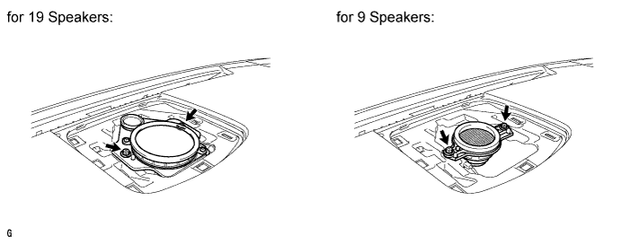
INSTALL FRONT NO. 2 SPEAKER ASSEMBLY
-
Connect the connector.
-
Temporarily install the speaker by aligning speaker with the positioning pins of the instrument panel.
-
Install the speaker with the 2 bolts.
Note
-
Do not touch the cone part of the speaker.
-
When installing the speaker to the instrument panel, be careful that the wires do not get caught between parts.
-
-
-
INSTALL NO. 1 INSTRUMENT PANEL SPEAKER PANEL SUB-ASSEMBLY
-
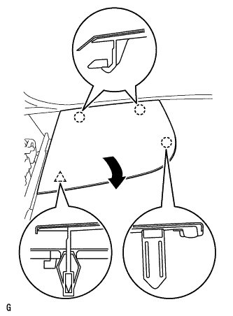
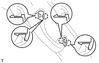
Hook the 2 claws on the far side to the instrument panel to attach them. Then, lower the panel towards the rear of the vehicle in the direction of the arrow, and attach the claw and clip on the front side to install the panel.
-
-
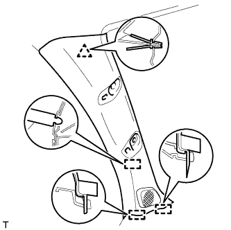
INSTALL FRONT PILLAR GARNISH LH
-
Connect the speaker connector.
-
Attach the clip and 3 guides to install the front pillar garnish.
-
-
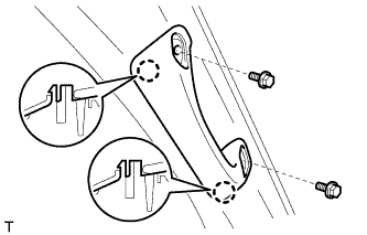
INSTALL FRONT ASSIST GRIP SUB-ASSEMBLY
Tech Tips
Use the same procedure to install the front assist grip on the other side.
-
Attach the 2 claws to install the front assist grip.
-
Install the 2 bolts.
-
Attach the 4 claws to install the 2 assist grip plugs.
-
-
INSTALL FRONT NO. 4 SPEAKER ASSEMBLY
-
Connect the speaker connector.
-
Temporarily install the speaker by aligning speaker with the positioning pins of the instrument panel.
-
Install the speaker with the 2 bolts.
Note
-
Do not touch the cone part of the speaker.
-
When installing the speaker to the instrument panel, be careful that the wires do not get caught between parts.
-
-
-
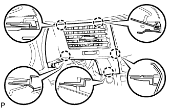
INSTALL NO. 1 SPEAKER OPENING COVER ASSEMBLY
-
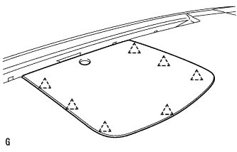
Attach the 7 clips to install the opening cover.
-
-
INSTALL MULTI-DISPLAY ASSEMBLY WITH BRACKET
-
Connect the connectors.
-
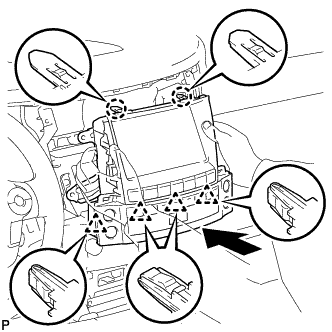
Insert the multi-display assembly with bracket to attach the 2 claws and 4 clips on its backside.
Note
When inserting the multi-display assembly, do not press the knobs on it.
-
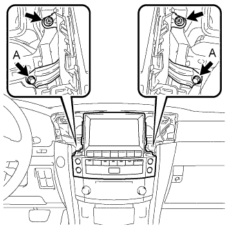
Install the multi-display assembly with the 2 screws and 2 bolts.
- Torque:
- for bolts labeled A
- 12 N*m { 122 kgf*cm, 8 ft.*lbf }
-
-
INSTALL NO. 4 INSTRUMENT PANEL REGISTER ASSEMBLY
-
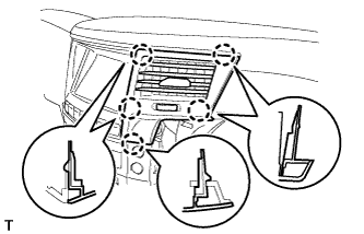
Attach the 5 claws to install the register.
-
-
INSTALL NO. 3 INSTRUMENT PANEL REGISTER ASSEMBLY
-
Attach the 5 claws to install the register.
-
-
CONNECT CABLE TO NEGATIVE BATTERY TERMINAL
Note
When disconnecting the cable, some systems need to be initialized after the cable is reconnected Click here.
-
INSTALL ENGINE ROOM SIDE COVER LH
-
Install the engine room side cover LH with the 7 clips.
-