REAR SEAT ENTERTAINMENT SYSTEM (for Seatback) TERMINALS OF ECU

-
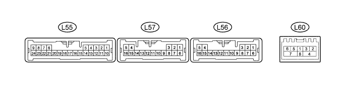
CHECK MULTI-DISPLAY CONTROLLER SUB-ASSEMBLY
Tech Tips
Perform the check from the rear of the connector while it is connected to the multi-display controller sub-assembly.
Terminal No. (Symbol) Wiring Color Terminal Description Condition Specified Condition L55-2 (MUT1) - L56-14 (GND) B - W-B Mute signal RSE playing → Source changed 3.5 V or higher → Below 1 V L55-3 (HP1R) - L56-14 (GND) B - W-B RSE sound signal RSE playing Waveform synchronized with sound is output L55-4 (SLD5) - L56-14 (GND) Shielded - W-B Shield ground Always Below 1 V L55-5 (HP1L) - L56-14 (GND) W - W-B RSE sound signal RSE playing Waveform synchronized with sound is output L55-6 (MUT2) - L56-14 (GND) W - W-B Mute signal RSE playing → Source changed 3.5 V or higher → Below 1 V L55-7 (HP2R) - L56-14 (GND) B - W-B RSE sound signal RSE playing Waveform synchronized with sound is output L55-8 (SLD6) - L56-14 (GND) Shielded - W-B Shield ground Always Below 1 V L55-9 (HP2L) - L56-14 (GND) W - W-B RSE sound signal RSE playing Waveform synchronized with sound is output L55-10 (TX1+) G AVC-LAN communication signal - - L55-11 (TX1-) L AVC-LAN communication signal - - L55-12 (TX2+) G AVC-LAN communication signal - - L55-13 (TX2-) L AVC-LAN communication signal - - L55-15 (SLD1) - Body ground Shielded - Body ground Shield ground Always Below 1 V L55-16 (R1+) - L56-14 (GND) B - W-B Sound signal RSE playing Waveform synchronized with sound signal is output L55-17 (R1-) - L56-14 (GND) W - W-B Sound signal RSE playing Waveform synchronized with sound signal is output L55-18 (L1+) - L56-14 (GND) G - W-B Sound signal RSE playing Waveform synchronized with sound signal is output L55-19 (L1-) - L56-14 (GND) R - W-B Sound signal RSE playing Waveform synchronized with sound signal is output L55-20 (SLD2) - Body ground Shielded - Body ground Shield ground Always Below 1 V L55-21 (R2+) - L56-14 (GND) B - W-B Sound signal RSE playing Waveform synchronized with sound signal is output L55-22 (R2-) - L56-14 (GND) W - W-B Sound signal RSE playing Waveform synchronized with sound signal is output L55-23 (L2+) - L56-14 (GND) G - W-B Sound signal RSE playing Waveform synchronized with sound signal is output L55-24 (L2-) - L56-14 (GND) R - W-B Sound signal RSE playing Waveform synchronized with sound signal is output L56-1 (+B) - L56-14 (GND) L - W-B Battery Always 11 to 14 V L56-2 (PWR2) - L56-14 (GND) P - W-B Power supply for television display assembly LH Engine switch on (IG) 11 to 14 V L56-3 (PWR1) - L56-14 (GND) G - W-B Power supply for television display assembly RH Engine switch on (IG) 11 to 14 V L56-4 (NTS4) - L56-14 (GND) B - W-B DVD image signal DVD playing Waveform synchronized with display signal is output L56-5 (SGN4) - Body ground W - Body ground DVD image signal ground Always Below 1 V L56-6 (+B2) - L56-14 (GND) L - W-B Battery Always 11 to 14 V L56-8 (VMTR) - L56-14 (GND) G - W-B Visual mute signal RSE playing → Source changed 3.5 V or higher → Below 1 V L56-9 (MD0) - L56-14 (GND) V - W-B LH/RH display recognition signal Always Below 1 V L56-10 (GND2) - L56-14 (GND) GR - W-B Ground Always Below 1 V L56-11 (GND4) - Body ground SB - Body ground Ground Always Below 1 V L56-12 (GND1) - L56-14 (GND) R - W-B Ground Always Below 1 V L56-13 (GND3) - Body ground L - Body ground Ground Always Below 1 V L56-14 (GND) - Body ground W-B - Body ground Ground Always Below 1 V L56-15 (GND5) - Body ground BR - Body ground Ground Always Below 1 V L56-16 (SLD4) - Body ground Shielded - Body ground Shield ground Always Below 1 V L57-1 (SGN5) - Body ground Shielded - Body ground Shield ground Always Below 1 V L57-2 (VD) - L56-14 (GND) B - W-B Video signal External device playing (when video terminal used) Waveform synchronized with sound signal is output L57-3 (VG) - Body ground W - Body ground Video signal ground Always Below 1 V L57-4 (VMT1) - L56-14 (GND) LG -W-B Visual mute signal Display operating → Source changed 3.5 V or higher → Below 1 V L57-5 (VMT2) - L56-14 (GND) G - W-B Visual mute signal Display operating → Source changed 3.5 V or higher → Below 1 V L57-6 (R+) - L56-14 (GND) W - W-B Sound signal External device playing (when video terminal used) Waveform synchronized with sound signal is output L57-7 (L+) - L56-14 (GND) B - W-B Sound signal External device playing (when video terminal used) Waveform synchronized with sound signal is output L57-8 (SGN3) - L56-14 (GND) R - W-B Sound signal ground Always Below 1 V L57-9 (SGN6) - Body ground Shielded - Body ground Video terminal detection ground Always Below 1 V L57-10 (ADPI) - L56-14 (GND) R - W-B Video terminal connection detection signal External device connected Below 1 V L57-11 (NTS1) - L56-14 (GND) B - W-B Display signal RSE playing Waveform synchronized with display signal is output L57-12 (SGN1) - L56-14 (GND) W - W-B Display signal ground Always Below 1 V L57-13 (SLDA) - Body ground Shielded - Body ground Shield ground Always Below 1 V L57-14 (NTS2) - L56-14 (GND) B - W-B Display signal RSE playing Waveform synchronized with display signal is output L57-15 (SGN2) - Body ground W - Body ground Display signal ground Always Below 1 V L57-16 (SLDB) - Body ground Shielded - Body ground Shield ground Always Below 1 V L60-2 (MI+) B MOST communication signal - - L60-3 (MI-) B MOST communication signal - - L60-4 (SLDI) - Body ground Shielded - Body ground Shield ground Always Below 1 V L60-5 (MO+) B MOST communication signal - - L60-6 (MO-) B MOST communication signal - - L60-7 (SLDO) - Body ground Shielded - Body ground Shield ground Always Below 1 V L60-8 (WUI) - L56-14 (GND) W - W-B MOST communication wake up signal Engine switch on (ACC) 4.5 V or higher Engine switch off Below 1 V -
CHECK TELEVISION DISPLAY ASSEMBLY LH

Tech Tips
Perform the check from the rear of the connector while it is connected to the television display assembly LH.
Terminal No. (Symbol) Wiring Color Terminal Description Condition Specified Condition c61-1 (R2+) - c61-20 (GND2) B - SB Sound signal RSE playing Waveform synchronized with sound signal is output c61-2 (R2-) - c61-20 (GND2) W - SB Sound signal RSE playing Waveform synchronized with sound signal is output c61-3 (L2+) - c61-20 (GND2) G - SB Sound signal RSE playing Waveform synchronized with sound signal is output c61-4 (L2-) - c61-20 (GND2) R - SB Sound signal RSE playing Waveform synchronized with sound signal is output c61-5 (MUT2) - c61-20 (GND2) W - SB Mute signal RSE playing → Source changed 3.5 V or higher → Below 1 V c61-7 (MUT1) - c61-20 (GND2) G - SB Visual mute signal RSE playing → Source changed 3.5 V or higher → Below 1 V c61-8 (TX2+) G AVC-LAN communication signal - - c61-9 (TX2-) L AVC-LAN communication signal - - c61-10 (NTSC) - c61-20 (GND2) B - SB Display signal RSE playing Waveform synchronized with display signal is output c61-12 (PWR2) - c61-20 (GND2) P - SB Power supply for television display assembly LH Display operating 11 to 14 V c61-13 (SLD2) - Body ground Shielded - Body ground Shield ground Always Below 1 V c61-19 (GND) - Body ground GR - Body ground Ground Always Below 1 V c61-20 (GND2) - Body ground SB - Body ground Ground Always Below 1 V c61-21 (SLD) - Body ground Shielded - Body ground Shield ground Always Below 1 V c61-22 (SGN2) - Body ground W - Body ground Display signal ground Always Below 1 V -
CHECK TELEVISION DISPLAY ASSEMBLY RH

Tech Tips
Perform the check from the rear of the connector while it is connected to the television display assembly RH.
Terminal No. (Symbol) Wiring Color Terminal Description Condition Specified Condition c60-1 (R1+) - c60-20 (GND4) B - L Sound signal RSE playing Waveform synchronized with sound signal is output c60-2 (R1-) - c60-20 (GND4) W - L Sound signal RSE playing Waveform synchronized with sound signal is output c60-3 (L1+) - c60-20 (GND4) G - L Sound signal RSE playing Waveform synchronized with sound signal is output c60-4 (L1-) - c60-20 (GND4) R - L Sound signal RSE playing Waveform synchronized with sound signal is output c60-5 (MUTE) - c60-20 (GND4) LG - L Mute signal RSE playing → Source changed 3.5 V or higher → Below 1 V c60-6 (MD0) - c60-20 (GND4) GR - L LH/RH display recognition signal Always Below 1 V c60-7 (VMTR) - c60-20 (GND4) SB - L Visual mute signal RSE playing → Source changed 3.5 V or higher → Below 1 V c60-8 (TX1+) L AVC-LAN communication signal - - c60-9 (TX1-) LG AVC-LAN communication signal - - c60-10 (VV1+) - c60-20 (GND4) W - L Display signal RSE playing Waveform synchronized with display signal is output c60-12 (PWR1) - c60-20 (GND4) V - L Power supply for television display assembly RH Display operating 11 to 14 V c60-13 (SLD1) - Body ground Shielded - Body ground Shield ground Always Below 1 V c60-19 (GND6) - Body ground P - Body ground Ground Always Below 1 V c60-20 (GND4) - Body ground L - Body ground Ground Always Below 1 V c60-21 (VVG1) - Body ground Shielded - Body ground Shield ground Always Below 1 V c60-22 (VV1-) - Body ground B - Body ground Display signal ground Always Below 1 V -
CHECK MULTI-MEDIA MODULE RECEIVER ASSEMBLY Click here
-
CHECK STEREO COMPONENT AMPLIFIER ASSEMBLY Click here