AUDIO AND VISUAL SYSTEM Microphone Circuit between Microphone and Radio Receiver
DESCRIPTION
-
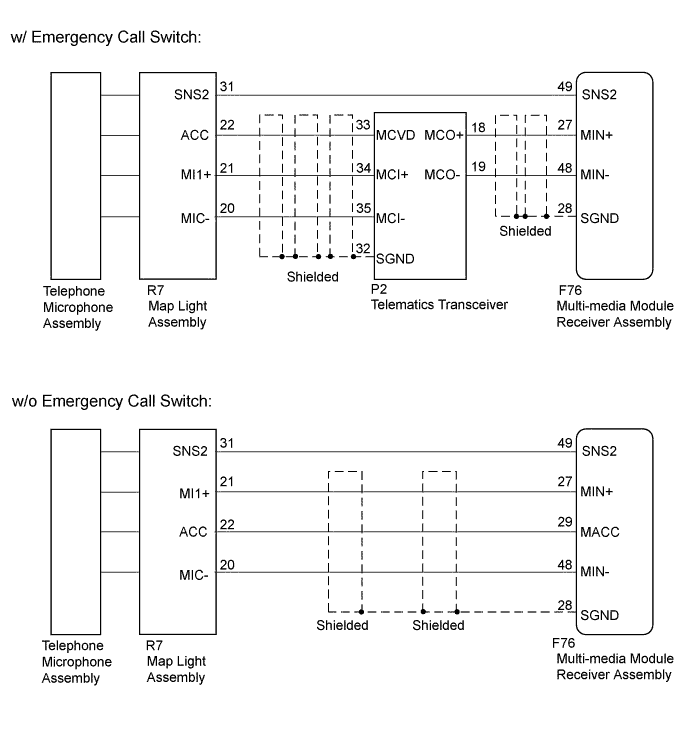
The multi-media module receiver assembly and map light assembly (telephone microphone assembly) are connected to each other using the microphone connection detection signal lines.
-
Using this circuit, the multi-media module receiver assembly sends power to the map light assembly (telephone microphone assembly), and the map light assembly (telephone microphone assembly) sends microphone signals to the multi-media module receiver assembly (w/o Emergency Call Switch).
-
Using this circuit, the telematics transceiver sends power to the map light assembly (telephone microphone assembly), and the map light assembly (telephone microphone assembly) sends microphone signals to the multi-media module receiver assembly via the telematics transceiver (w/ Emergency Call Switch).
WIRING DIAGRAM
INSPECTION PROCEDURE
Tech Tips
When replacing the multi-media module receiver assembly or the telematics transceiver, perform the vehicle contract setting Click here.
PROCEDURE
-
CONFIRM MODEL
-
Choose the model to be inspected.
Model Model Proceed to w/o Emergency Call Switch A w/ Emergency Call Switch B
B 
A 
-
-
CHECK HARNESS AND CONNECTOR (MULTI-MEDIA MODULE RECEIVER ASSEMBLY - MAP LIGHT ASSEMBLY)
-
Disconnect the F76 multi-media module receiver assembly connector.
-
Disconnect the R7 map light assembly connector.
-
Measure the resistance according to the value(s) in the table below.
Standard Resistance Tester Connection Condition Specified Condition F76-27 (MIN+) - R7-21 (MI1+) Always Below 1 Ω F76-29 (MACC) - R7-22 (ACC) Always Below 1 Ω F76-48 (MIN-) - R7-20 (MIC-) Always Below 1 Ω F76-49 (SNS2) - R7-31 (SNS2) Always Below 1 Ω F76-27 (MIN+) - Body ground Always 10 kΩ or higher F76-28 (SGND) - Body ground Always 10 kΩ or higher F76-29 (MACC) - Body ground Always 10 kΩ or higher F76-48 (MIN-) - Body ground Always 10 kΩ or higher F76-49 (SNS2) - Body ground Always 10 kΩ or higher
NG 
REPLACE MULTI-MEDIA MODULE RECEIVER ASSEMBLY Click here
OK
-
-
CHECK MULTI-MEDIA MODULE RECEIVER ASSEMBLY
-
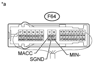
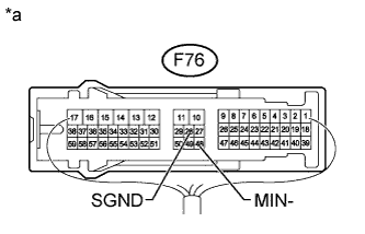
Text in Illustration *a Component with harness connected
(Multi-media Module Receiver Assembly)
Measure the voltage according to the value(s) in the table below.
Standard Voltage Tester Connection Switch Condition Specified Condition F76-29 (MACC) - Body ground Engine switch on (ACC) 4 to 6 V -
Measure the resistance according to the value(s) in the table below.
Standard Resistance Tester Connection Condition Specified Condition F76-28 (SGND) - Body ground Always Below 1 Ω F76-48 (MIN-) - Body ground Always Below 1 Ω
NG
REPLACE MULTI-MEDIA MODULE RECEIVER ASSEMBLY Click here
OK
-
-
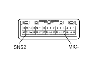
INSPECT MAP LIGHT ASSEMBLY
-
Remove the map light assembly Click here.
-
Measure the resistance according to the value(s) in the table below.
Standard Resistance Tester Connection Condition Specified Condition 20 (MIC-) - 31 (SNS2) Always Below 1 Ω
NG
CHECK TELEPHONE MICROPHONE ASSEMBLY Click here
OK
-
-
CHECK MAP LIGHT ASSEMBLY
-
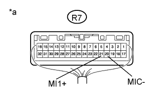
Text in Illustration *a Component with harness connected
(Map Light Assembly)
Turn the engine switch on (ACC).
-
Connect an oscilloscope to terminals R7-21 (MI1+) and R7-20 (MIC-) of the map light assembly connector.
-
Check the waveform of the telephone microphone assembly using the oscilloscope.
Result Result Proceed to A waveform synchronized with the voice input to the map light assembly is output. A A waveform synchronized with the voice input to the map light assembly is not output. B
B
CHECK TELEPHONE MICROPHONE ASSEMBLY Click here
A 
PROCEED TO NEXT SUSPECTED AREA SHOWN IN PROBLEM SYMPTOMS TABLE Click here
-
-
CHECK TELEPHONE MICROPHONE ASSEMBLY
-
Replace the telephone microphone assembly with a new or normally functioning one Click here.
-
Check if the same malfunction recurs.
Result Result Proceed to Malfunction does not recur
(returns to normal).
A Malfunction recurs. B
B
REPLACE MAP LIGHT ASSEMBLY Click here
A
END (TELEPHONE MICROPHONE ASSEMBLY IS DEFECTIVE)
-
-
CHECK HARNESS AND CONNECTOR (MULTI-MEDIA MODULE RECEIVER ASSEMBLY - MAP LIGHT ASSEMBLY)
-
Disconnect the F76 multi-media module receiver assembly connector.
-
Disconnect the R7 map light assembly connector.
-
Measure the resistance according to the value(s) in the table below.
Standard Resistance Tester Connection Condition Specified Condition F76-49 (SNS2) - R7-31 (SNS2) Always Below 1 Ω
NG
REPAIR OR REPLACE HARNESS OR CONNECTOR
OK
-
-
CHECK HARNESS AND CONNECTOR (MULTI-MEDIA MODULE RECEIVER ASSEMBLY - TELEMATICS TRANSCEIVER)
-
Disconnect the F76 multi-media module receiver assembly connector.
-
Disconnect the P2 telematics transceiver connector.
-
Measure the resistance according to the value(s) in the table below.
Standard Resistance Tester Connection Condition Specified Condition F76-27 (MIN+) - P2-18 (MCO+) Always Below 1 Ω F76-48 (MIN-) - P2-19 (MCO-) Always Below 1 Ω F76-27 (MIN+) - Body ground Always 10 kΩ or higher F76-48 (MIN-) - Body ground Always 10 kΩ or higher F76-28 (SGND) - Body ground Always 10 kΩ or higher
NG
REPAIR OR REPLACE HARNESS OR CONNECTOR
OK
-
-
CHECK HARNESS AND CONNECTOR (TELEMATICS TRANSCEIVER - MAP LIGHT ASSEMBLY)
-
Disconnect the P2 telematics transceiver connector.
-
Disconnect the R7 map light assembly connector.
-
Measure the resistance according to the value(s) in the table below.
Standard Resistance Tester Connection Condition Specified Condition P2-33 (MCVD) - R7-22 (ACC) Always Below 1 Ω P2-34 (MCI+) - R7-21 (MI1+) Always Below 1 Ω P2-35 (MCI-) - R7-20 (MIC-) Always Below 1 Ω P2-33 (MCVD) - Body ground Always 10 kΩ or higher P2-34 (MCI+) - Body ground Always 10 kΩ or higher P2-35 (MCI-) - Body ground Always 10 kΩ or higher P2-32 (SGND) - Body ground Always 10 kΩ or higher
NG
REPAIR OR REPLACE HARNESS OR CONNECTOR
OK
-
-
CHECK MULTI-MEDIA MODULE RECEIVER ASSEMBLY
-
Text in Illustration *a Component with harness connected
(Multi-media Module Receiver Assembly)
Disconnect the P2 telematics transceiver connector.
-
Measure the resistance according to the value(s) in the table below.
Standard Resistance Tester Connection Condition Specified Condition F76-28 (SGND) - Body ground Always Below 1 Ω F76-48 (MIN-) - Body ground Always Below 1 Ω
NG
REPLACE MULTI-MEDIA MODULE RECEIVER ASSEMBLY Click here
OK
-
-
CHECK TELEMATICS TRANSCEIVER
-
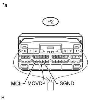
Text in Illustration *a Component with harness connected
(Telematics Transceiver)
Measure the voltage according to the value(s) in the table below.
Standard Voltage Tester Connection Switch Condition Specified Condition P2-33 (MCVD) - Body ground Engine switch on (ACC) 4 to 6 V -
Measure the resistance according to the value(s) in the table below.
Standard Resistance Tester Connection Condition Specified Condition P2-32 (SGND) - Body ground Always Below 1 Ω P2-35 (MCI-) - Body ground Always Below 1 Ω
NG
REPLACE TELEMATICS TRANSCEIVER Click here
OK
-
-
INSPECT MAP LIGHT ASSEMBLY
-
Remove the map light assembly Click here.
-
Measure the resistance according to the value(s) in the table below.
Standard Resistance Tester Connection Condition Specified Condition 20 (MIC-) - 31 (SNS2) Always Below 1 Ω
NG
CHECK TELEPHONE MICROPHONE ASSEMBLY Click here
OK
-
-
CHECK MAP LIGHT ASSEMBLY
-
Text in Illustration *a Component with harness connected
(Map Light Assembly)
Turn the engine switch on (ACC).
-
Connect an oscilloscope to terminals R7-21 (MI1+) and R7-20 (MIC-) of the map light assembly connector.
-
Check the waveform of the telephone microphone assembly using the oscilloscope.
Result Result Proceed to A waveform synchronized with the voice input to the map light assembly is output. A A waveform synchronized with the voice input to the map light assembly is not output. B
B
CHECK TELEPHONE MICROPHONE ASSEMBLY Click here
A
PROCEED TO NEXT SUSPECTED AREA SHOWN IN PROBLEM SYMPTOMS TABLE Click here
-
-
CHECK TELEPHONE MICROPHONE ASSEMBLY
-
Replace the telephone microphone assembly with a new or normally functioning one Click here.
-
Check if the same malfunction recurs.
Result Result Proceed to Malfunction does not recur
(returns to normal).
A Malfunction recurs. B
B
REPLACE MAP LIGHT ASSEMBLY Click here
A
END (TELEPHONE MICROPHONE ASSEMBLY IS DEFECTIVE)
-