STEERING LINKAGE INSTALLATION

-
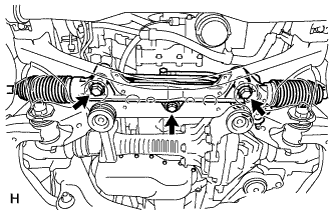
INSTALL POWER STEERING LINK ASSEMBLY
-
Install the power steering link with the 3 bolts and 3 nuts.
- Torque:
- 120 N*m { 1224 kgf*cm, 89 ft.*lbf }
Tech Tips
Hold the bolts and tighten the nuts to install the power steering link.
Note
Align the center bush so that the protrusion aligns with the longitudinal axis of the vehicle.
-
-
INSTALL FRONT SUSPENSION REBOUND STOPPER SUB-ASSEMBLY LH
-
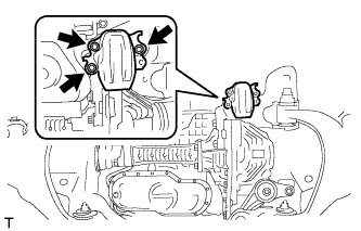
Remove the 3 bolts and suspension rebound stopper LH.
-
-
INSTALL FRONT SUSPENSION REBOUND STOPPER SUB-ASSEMBLY RH
-
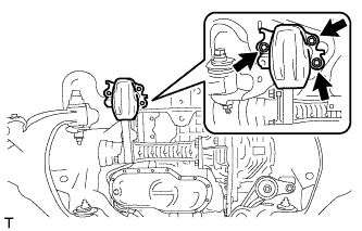
Install the suspension rebound stopper RH with 3 bolts.
- Torque:
- 58 N*m { 591 kgf*cm, 43 ft.*lbf }
-
-
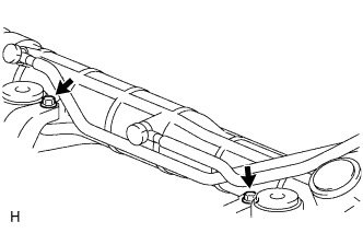
INSTALL PRESSURE FEED TUBE ASSEMBLY
-
Install the pressure feed tube clamp with the 2 bolts.
- Torque:
- 18 N*m { 184 kgf*cm, 13 ft.*lbf }
-
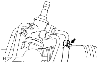
Install the clamp and connect the pressure feed tube (return tube side) to the power steering link.
-
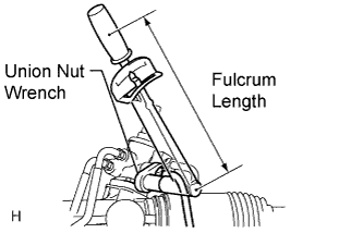
Using a union nut wrench, connect the pressure feed tube (pressure feed tube side) to the power steering link.
- Torque:
- 44 N*m { 449 kgf*cm, 32 ft.*lbf }
Note
Use the formula to calculate special torque values for situations where a union nut wrench is combined with a torque wrench Click here.
-
-
INSTALL TIE ROD END SUB-ASSEMBLY LH
-
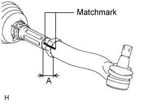
Align the matchmarks of the tie rod and rack end, and temporarily install the tie rod with the lock nut.
Tech Tips
After adjusting toe-in, tighten the lock nut.
- Torque:
- 82 N*m { 836 kgf*cm, 60 ft.*lbf }
-
Check that length A is the same as the length measured previously.
-
-
INSTALL TIE ROD END SUB-ASSEMBLY RH
Tech Tips
Use the same procedures described for the RH side.
-
CONNECT TIE ROD END SUB-ASSEMBLY LH
-
Connect the tie rod end LH to the steering knuckle with the nut.
- Torque:
- 69 N*m { 704 kgf*cm, 51 ft.*lbf }
-
Install a new cotter pin.
Tech Tips
If the holes for the cotter pin are not aligned, tighten the nut up to another 60°.
-
-
CONNECT TIE ROD END SUB-ASSEMBLY RH
Tech Tips
Use the same procedures described for the RH side.
-
CONNECT NO. 2 STEERING INTERMEDIATE SHAFT
-
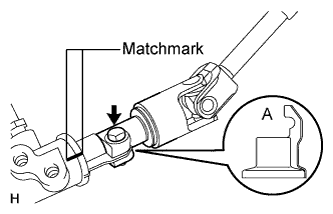
Align the part of the dust cover labeled A with the No. 2 steering intermediate shaft, and install the No. 2 steering intermediate shaft assembly to the steering link assembly.
-
Install the bolt.
- Torque:
- 35 N*m { 360 kgf*cm, 26 ft.*lbf }
Note
Be careful not to damage the dust cover.
-
-
INSTALL FRONT STABILIZER BAR
-
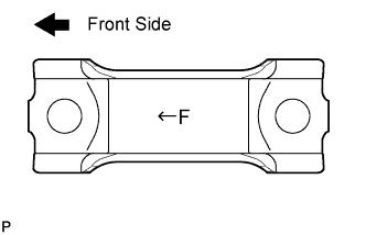
Set the stabilizer bracket so that the arrow mark is facing the front side of the vehicle.
-
Temporarily install the 2 stabilizer brackets and front stabilizer bar with the 4 bolts.
-
-
TEMPORARILY INSTALL FRONT STABILIZER LINK ASSEMBLY RH
-
Temporarily install the stabilizer link with the nut and bolt.
-
Tighten the nut.
- Torque:
- 128 N*m { 1305 kgf*cm, 94 ft.*lbf }
-
-
TEMPORARILY INSTALL FRONT STABILIZER LINK ASSEMBLY LH
-
Temporarily install the stabilizer link with the nut and bolt.
-
Tighten the nut.
- Torque:
- 128 N*m { 1305 kgf*cm, 94 ft.*lbf }
-
-
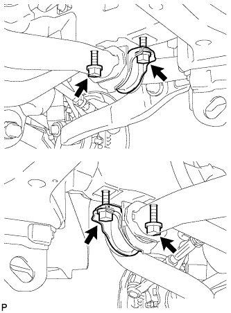
TIGHTEN FRONT NO. 1 STABILIZER BRACKET LH
-
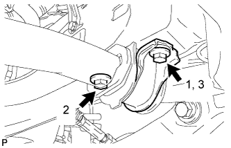
Tighten the 2 bolts.
- Torque:
- 87 N*m { 887 kgf*cm, 64 ft.*lbf }
Note
Tighten the bolts in 3 steps, in the order shown in the illustration.
-
-
TIGHTEN FRONT NO. 1 STABILIZER BRACKET RH
-
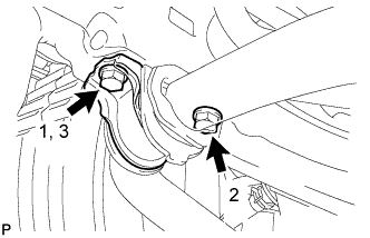
Tighten the 2 bolts.
- Torque:
- 87 N*m { 887 kgf*cm, 64 ft.*lbf }
Note
Tighten the bolts in 3 steps, in the order shown in the illustration.
-
-
STABILIZE SUSPENSION
-
Install the front wheels.
- Torque:
- 131 N*m { 1336 kgf*cm, 97 ft.*lbf }
-
Lower the vehicle.
-
Press down on the vehicle several times to stabilize the suspension.
-
-
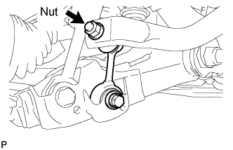
TIGHTEN FRONT STABILIZER LINK ASSEMBLY LH
-
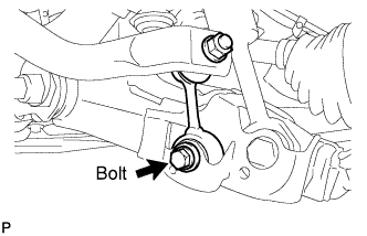
Tighten the bolt.
- Torque:
- 135 N*m { 1376 kgf*cm, 100 ft.*lbf }
Note
Perform this procedure with all 4 wheels on the ground.
-
-
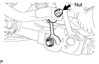
TIGHTEN FRONT STABILIZER LINK ASSEMBLY RH
-
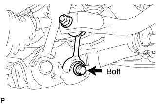
Tighten the bolt.
- Torque:
- 135 N*m { 1376 kgf*cm, 100 ft.*lbf }
Note
Perform this procedure with all 4 wheels on the ground.
-
-
INSTALL ENGINE ASSEMBLY
for 1UR-FE:
for 3UR-FE:
-
BLEED POWER STEERING FLUID
-
Check the fluid level.
-
Jack up the front of the vehicle and support it with stands.
-
Turn the steering wheel.
-
With the engine stopped, turn the wheel slowly from lock to lock several times.
-
-
Lower the vehicle.
-
Start the engine.
-
Idle the engine for a few minutes.
-
Turn the steering wheel.
-
With the engine idling, turn the wheel left or right to the full lock position and keep it there for 2 to 3 seconds, then turn the wheel to the opposite full lock position and keep it there for 2 to 3 seconds.*1
-
Repeat *1 several times.
Note
For vehicles with VGRS, if the steering wheel is turned from lock to lock repeatedly, the system may stop operating and the amount of rotation before the steering wheel locks may increase due to operation of the overheating prevention function. When the system temperature drops, the system operation automatically returns to normal.
-
-
Stop the engine.
-
Check for foaming or emulsification.
If the system has to be bled twice because of foaming or emulsification, check for fluid leaks in the system.
-
Check the fluid level.
-
-
CHECK POWER STEERING FLUID LEVEL
-
Keep the vehicle horizontal.
-
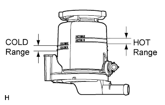
With the engine stopped, check the fluid level in the reservoir.
If necessary, add fluid.
Fluid ATF DEXRON II or III Tech Tips
If the fluid is hot, check that the fluid level is within the HOT range. If the fluid is cold, check that the fluid level is within the COLD range.
-
Start the engine and idle it.
-
Turn the steering wheel from lock to lock several times to raise the fluid temperature.
Fluid temperature 80°C (176°F) -
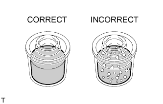
Check for foaming or emulsification.
If foaming or emulsification is identified, bleed the power steering system.
-
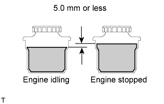
With the engine idling, measure the fluid level in the reservoir.
-
Stop the engine.
-
Wait a few minutes and remeasure the fluid level in the reservoir.
Maximum fluid level rise 5.0 mm (0.197 in.) If the fluid level rise is more than the maximum, bleed the power steering system.
-
Check the fluid level.
-
-
CHECK FOR POWER STEERING FLUID LEAK
-
INSTALL FRONT WHEELS
-
PLACE FRONT WHEELS FACING STRAIGHT AHEAD
Tech Tips
Perform this procedure with the front of the vehicle jacked up.
-
PERFORM VEHICLE HEIGHT OFFSET CALIBRATION
-
Perform the vehicle height offset calibration Click here.
-
-
ADJUST FRONT WHEEL ALIGNMENT
-
Adjust the front wheel alignment Click here.
-
-
ADJUST HEADLIGHT ASSEMBLY
-
Adjust the headlight Click here.
-