STEERING LINKAGE REMOVAL

-
PLACE FRONT WHEELS FACING STRAIGHT AHEAD
-
REMOVE ENGINE ASSEMBLY
for 3UR-FE:
for 1UR-FE:
-
REMOVE FRONT WHEELS
-
LOOSEN FRONT NO. 1 STABILIZER BRACKET LH
-
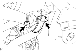
Loosen the 2 bolts of the front stabilizer brackets.
-
-
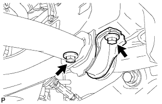
LOOSEN FRONT NO. 1 STABILIZER BRACKET RH
-

Loosen the 2 bolts of the front stabilizer brackets.
-
-
REMOVE FRONT STABILIZER LINK ASSEMBLY LH
-

Remove the bolt, nut and stabilizer link.
Tech Tips
If the ball joint turns together with the nut, use a 6 mm hexagon wrench to hold the stud.
-
-
REMOVE FRONT STABILIZER LINK ASSEMBLY RH
-

Remove the bolt, nut and stabilizer link.
Tech Tips
If the ball joint turns together with the nut, use a 6 mm hexagon wrench to hold the stud.
-
-
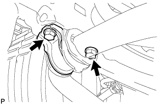
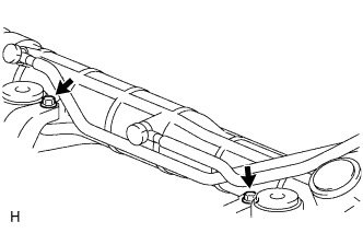
REMOVE FRONT NO. 1 STABILIZER BRACKET LH
-
Remove the 2 bolts and stabilizer bracket from the front frame assembly.
-
-
REMOVE FRONT NO. 1 STABILIZER BRACKET RH
-
Remove the 2 bolts and stabilizer bracket from the front frame assembly.
-
-
REMOVE FRONT STABILIZER BAR
-
Remove the front stabilizer bar from the frame assembly.
-
-
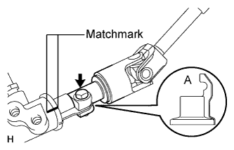
DISCONNECT NO. 2 STEERING INTERMEDIATE SHAFT
-
Loosen the bolt and remove the No. 2 intermediate shaft.
Tech Tips
If the dust cover is removed/installed or replaced, place matchmarks on the dust cover and steering link.
Note
It is possible to install the intermediate shaft to the same position it was removed from without placing matchmarks due to the dust cover part labeled A. Therefore, do not remove the dust cover from the steering link.
-
-
DISCONNECT TIE ROD END SUB-ASSEMBLY LH
-
Remove the cotter pin and nut.
-
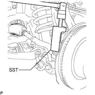
Using SST, disconnect the tie rod end LH from the steering knuckle.
- SST
- 09610-20012
Note
-
Do not damage the front disc brake dust cover.
-
Do not damage the ball joint dust cover.
-
Do not damage the steering knuckle.
-
-
DISCONNECT TIE ROD END SUB-ASSEMBLY RH
Tech Tips
Use the same procedures described for the LH side.
-
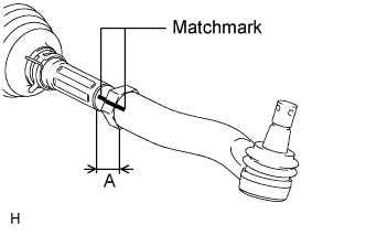
REMOVE TIE ROD END SUB-ASSEMBLY LH
-
Put matchmarks on the tie rod end LH and steering rack end.
-
Measure length A and record the measurement.
-
Remove the tie rod end.
-
-
REMOVE TIE ROD END SUB-ASSEMBLY RH
Tech Tips
Use the same procedures described for the LH side.
-
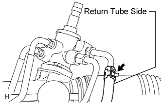
DISCONNECT PRESSURE FEED TUBE ASSEMBLY
-
Remove the clamp and disconnect the pressure feed tube (return tube side) from the power steering link.
-
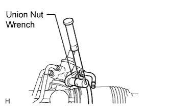
Using a union nut wrench, disconnect the pressure feed tube (pressure feed tube side) from the power steering link.
-
Remove the 2 bolts and disconnect the pressure feed tube clamp.
-
-
REMOVE FRONT SUSPENSION REBOUND STOPPER SUB-ASSEMBLY LH
-
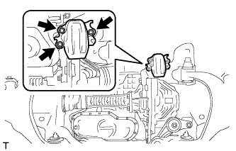
Remove the 3 bolts and suspension rebound stopper LH.
-
-
REMOVE FRONT SUSPENSION REBOUND STOPPER SUB-ASSEMBLY RH
-
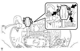
Remove the 3 bolts and suspension rebound stopper RH.
-
-
REMOVE POWER STEERING LINK ASSEMBLY
-
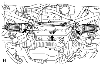
Remove the 3 bolts, 3 nuts and power steering link.
-