STEERING COLUMN ASSEMBLY REMOVAL

CAUTION:
Some of these service operations affect the SRS airbag system. Read the precautionary notices concerning the SRS airbag system before servicing the steering column Click here.
-
FRONT WHEELS FACING STRAIGHT AHEAD
-
PRECAUTION
Note
After turning the ignition switch off, waiting time may be required before disconnecting the cable from the battery terminal. Therefore, make sure to read the disconnecting the cable from the battery terminal notice before proceeding with work Click here.
-
DISCONNECT CABLE FROM NEGATIVE BATTERY TERMINAL
-
Disable the Autoaway/Return function by changing the customize parameter Click here.
Note
Record the current customize parameter setting (whether the AUTO TILT AWAY function is enabled or disabled) in order to restore the current setting after finishing the operation.
Tech Tips
Performing the above operation causes the AUTO TILT AWAY function to be disabled when the engine switch is turned off.
-
Turn the engine switch on (IG). Operate the tilt and telescopic switch to fully extend and lower the steering column assembly.
-
Turn the engine switch off and disconnect the cable from the negative (-) battery terminal.
CAUTION:
Wait at least 90 seconds after disconnecting the cable from the negative (-) battery terminal to disable the SRS system.
Note
When disconnecting the cable, some systems need to be initialized after the cable is reconnected Click here.
-
-
REMOVE LOWER NO. 3 STEERING WHEEL COVER
-
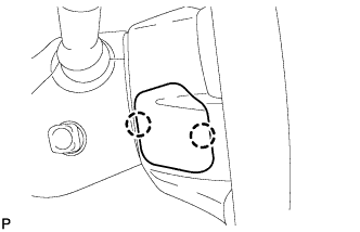
Detach the 2 claws and remove the steering wheel cover.
-
-
REMOVE LOWER NO. 2 STEERING WHEEL COVER
-
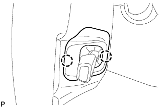
Detach the 2 claws and remove the steering wheel cover.
-
-
REMOVE STEERING PAD
-
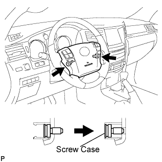
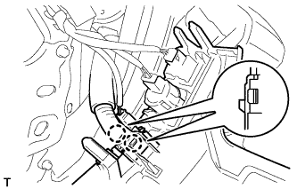
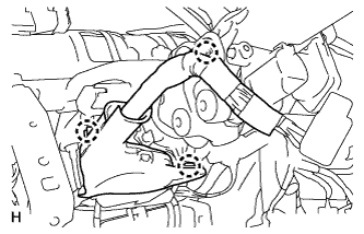
Using a T30 "TORX" socket wrench, loosen the 2 screws until the groove along the screw circumference catches on the screw case.
-
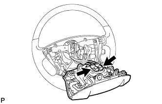
Pull out the steering pad from the steering wheel, as shown in the illustration. Then support the steering pad with one hand.
Note
When removing the steering pad, do not pull the airbag wire harness.
-
Disconnect the horn connector.
-
Disconnect the 2 connectors and remove the steering pad.
Note
When handling the airbag connector, take care not to damage the airbag wire harness.
-
-
REMOVE STEERING WHEEL ASSEMBLY
-
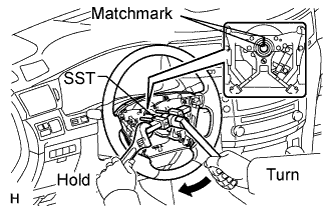
Remove the steering wheel set nut.
-
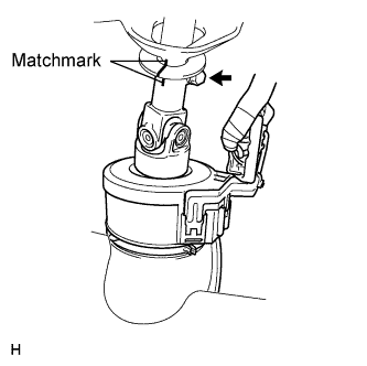
Put matchmarks on the steering wheel and main shaft.
-
Using SST, remove the steering wheel assembly.
- SST
- 09950-50013 ( 09951-05010, 09952-05010, 09953-05020, 09954-05011 )
-
-
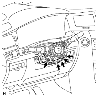
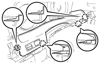
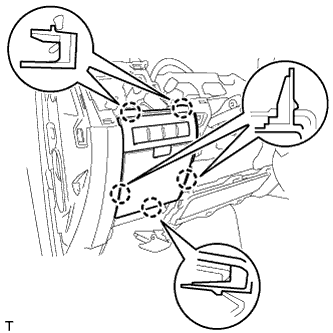
REMOVE LOWER STEERING COLUMN COVER
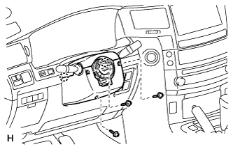
-
Remove the 3 screws.
-
Detach the 2 claws to remove the lower steering column cover.
Note
Do not damage the tilt and telescopic switch.
-
-
REMOVE UPPER STEERING COLUMN COVER
-
Detach the 4 clips.
-
Detach the claw to remove the upper steering column cover.
-
-
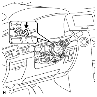
REMOVE TILT AND TELESCOPIC SWITCH
-
Disconnect the switch connector.
-
Using a screwdriver, detach the claw and pull out the switch.
Tech Tips
Tape the screwdriver tip before use.
Note
Pushing on the claw too hard will break the claw.
-
-
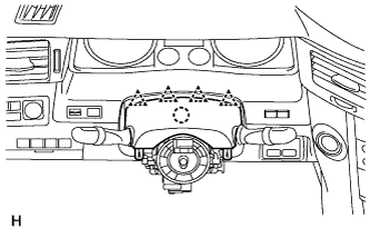
REMOVE COMBINATION SWITCH ASSEMBLY WITH SPIRAL CABLE SUB-ASSEMBLY
-
Disconnect the 5 connectors from the turn signal switch with spiral cable.
-
Using pliers, grip the claws of the clamp and remove the turn signal switch with spiral cable from the steering column.
-
-
REMOVE LOWER INSTRUMENT PANEL PAD SUB-ASSEMBLY LH
-
Detach the 8 claws.
-
Disconnect the connector and remove the panel pad.
-
-
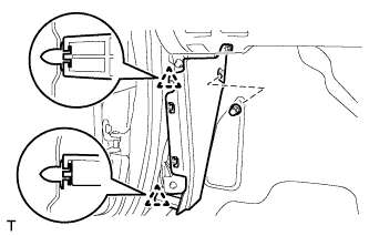
REMOVE INNER NO. 1 INSTRUMENT PANEL BRACKET COVER LH
-
Remove the clip.
-
Detach the clip and remove the cover.
-
-
REMOVE INSTRUMENT SIDE PANEL LH
-
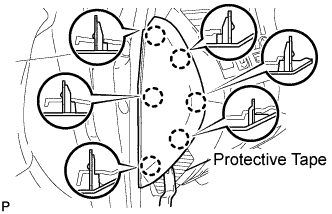
Place protective tape as shown in the illustration.
-
Using a moulding remover, detach the 6 claws and remove the side panel.
-
-
REMOVE NO. 1 INSTRUMENT PANEL REGISTER ASSEMBLY
-
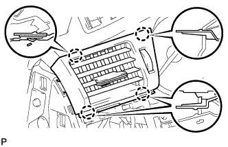
Detach the 4 claws and remove the register.
-
-
REMOVE NO. 3 INSTRUMENT PANEL REGISTER ASSEMBLY
-
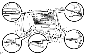
Detach the 5 claws and remove the register.
-
-
REMOVE NO. 1 SWITCH HOLE BASE
-
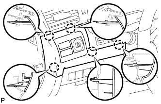
Detach the 5 claws.
-
Disconnect the connectors and remove the switch hole base.
-
-
REMOVE INSTRUMENT CLUSTER FINISH PANEL SUB-ASSEMBLY
-
Detach the 4 claws.
-
Disconnect the connectors and remove the finish panel.
-
-
REMOVE FRONT DOOR SCUFF PLATE LH
-
w/o Illumination:
-
Detach the 7 claws and 4 clips, and remove the scuff plate.
-
-
w/ Illumination:
-
Detach the 7 claws and 4 clips.
-
Disconnect the connector and remove the scuff plate.
-
-
-
REMOVE NO. 1 INSTRUMENT PANEL UNDER COVER SUB-ASSEMBLY
-
Remove the 2 screws.
-
Detach the 3 claws.
-
Remove the under cover and disconnect the connectors.
-
-
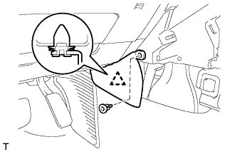
REMOVE COWL SIDE TRIM BOARD LH
-
Remove the cap nut.
-
Detach the 2 clips and remove the trim board.
-
-
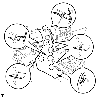
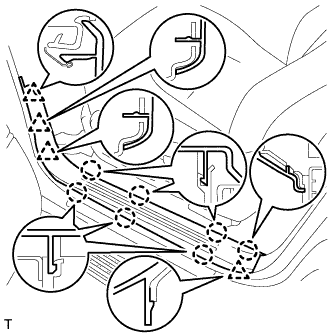
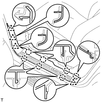
REMOVE LOWER NO. 1 INSTRUMENT PANEL FINISH PANEL
-
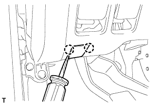
Using a screwdriver, detach the 2 claws and open the hole cover.
Tech Tips
Tape the screwdriver tip before use.
-
Remove the 2 bolts.
-
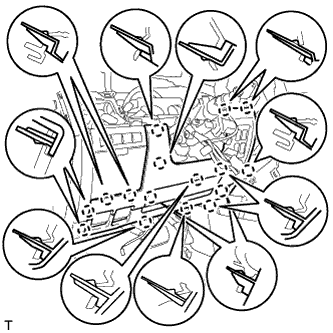
Detach the 16 claws.
-
Detach the 2 claws and remove the sensor.
-
Detach the 2 claws and disconnect the 2 control cables.
-
Remove the finish panel and then disconnect the connectors.
-
-
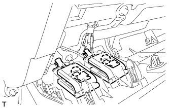
REMOVE INSTRUMENT PANEL BOX ASSEMBLY
-
Detach the 5 claws.
-
Remove the box and then disconnect the connectors.
-
-
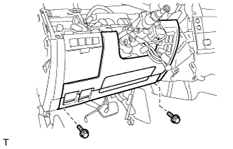
REMOVE DRIVER SIDE KNEE AIRBAG ASSEMBLY
-
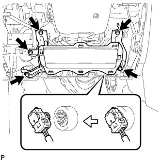
Remove the 5 bolts and driver side knee airbag.
-
Disconnect the connector.
Note
When handling the airbag connector, take care not to damage the airbag wire harness.
-
-
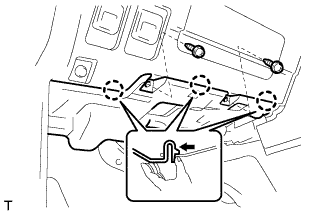
DISCONNECT WIRE HARNESS PROTECTOR AND WIRE HARNESS
-
Detach the 3 claws to disconnect the wire harness protector and wire harness.
-
-
REMOVE NO. 3 AIR DUCT SUB-ASSEMBLY
-
Remove the clip.
-
Detach the 2 claws and remove the duct.
-
-
REMOVE STEERING COLUMN ASSEMBLY
-
Put matchmarks on the steering actuator and steering column.
-
Remove the bolt.
-
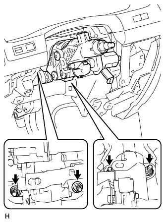
Remove the 4 nuts and steering column.
-
-
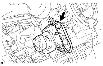
DISCONNECT STEERING ACTUATOR ASSEMBLY
-
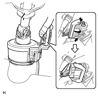
While pushing the claws on both sides of the connector, move the lock in the direction of the arrow.
-
Disconnect the connector.
-
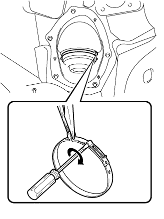
Hold the clamp with needle nose pliers, then insert a screwdriver and turn it in the direction shown in the illustration to remove the clamp of the steering column hole cover.
-
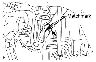
Put matchmarks on the steering actuator and No. 2 steering intermediate shaft.
-
Remove the bolt, and then pull out the actuator assembly toward the inside of the vehicle.
-
-
REMOVE STEERING COLUMN HOLE COVER SUB-ASSEMBLY
-
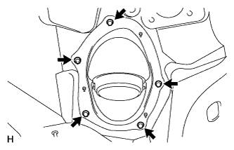
Remove the 4 bolts, nut and steering column hole cover.
-
-
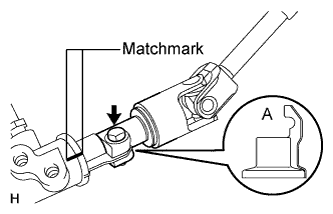
DISCONNECT NO. 2 STEERING INTERMEDIATE SHAFT
-
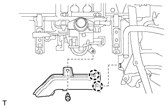
Loosen the bolt and remove the No. 2 intermediate shaft.
Tech Tips
If the dust cover is removed/installed or replaced, place matchmarks on the dust cover and steering link.
Note
It is possible to install the intermediate shaft to the same position it was removed from without placing matchmarks due to the dust cover part labeled A. Therefore, do not remove the dust cover from the steering link.
-